VUE
23
I – 3 T
u
rn
ing Specific Oper
ations
Setting Tool Offsets with Lock Axis Function
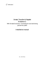
Example 2: LOCK AXIS
The LOCK AXIS function can be used to set a tool’s offset when a tool
is under load, and the diameter of the workpiece is not known.
The LOCK AXIS function is useful when determining tool data by
touching the workpiece. To avoid losing the position value when the
tool is retracted to measure the workpiece, this value can be stored by
pressing LOCK AXIS.
To use the LOCK AXIS function:
U
Press the TOOL hard key.
U
Select tool, and press ENTER.
U
Press the X axis key.
U
Turn a diameter in the X axis.
U
Press the LOCK AXIS soft key while the tool is still cutting.
U
Retract from the current position.
U
Turn the spindle off, and measure the workpiece diameter.
U
Enter the measured diameter, or radius, and press ENTER.
Remember to ensure the VUE is in diameter display mode (Ø).
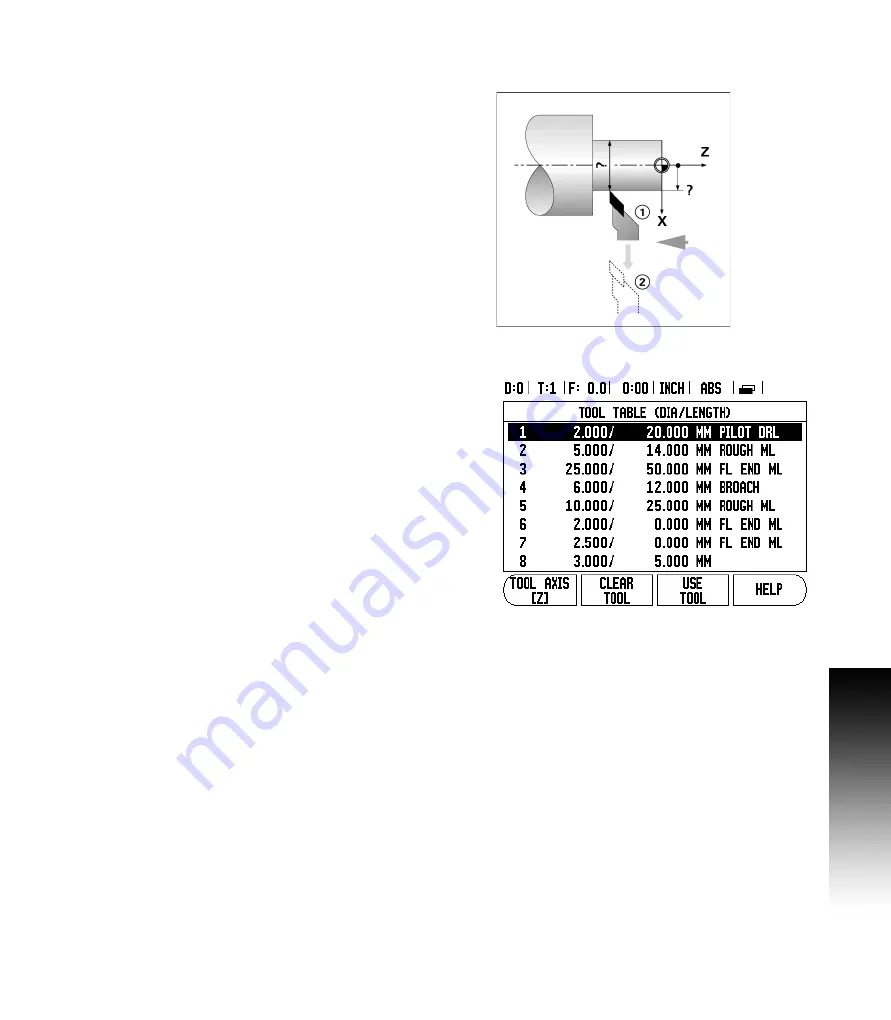
Calling a Tool from the Tool Table
U
To call a tool, press the TOOL hard key.
U
Use the UP/DOWN arrow keys to Cursor through the selection of
tools (1-16). Highlight the tool wanted.
U
Verify the proper tool has been called, and press either the use the
TOOL soft key, or the C key to exit.
Summary of Contents for VUE
Page 2: ......
Page 6: ...vi Readout Parameter Access Code ...
Page 8: ...viii VUE Fonts ...
Page 10: ...x ...
Page 14: ...xiv ...
Page 54: ...40 II 3 Dimensions ...
Page 57: ......