background image

Operation Manual - LR7 Wall Control

Document: 0525-075  

 Ver. 2 190912

Operation Manual

LR7 Wall Controller

28

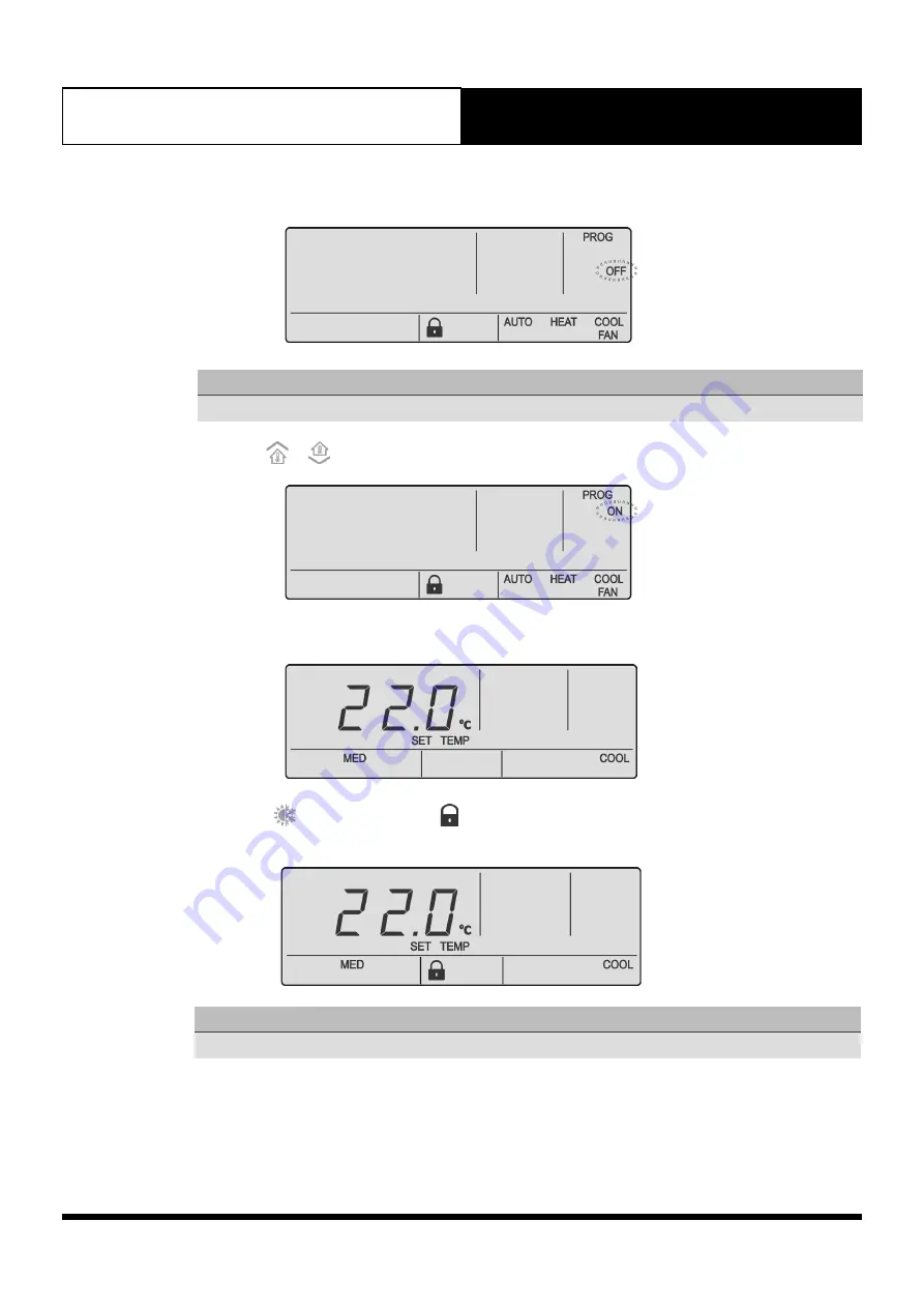
4.  Press the 

PROG


button to enter Program Menu 04.  

NOTE

Mode lock is Off by default.   

5.  Press the 


or 

 buttons to turn the Mode lock  

ON

6.  Press the 

PROG

 button to accept the selection. Press the 

EXIT

 button once to go back to the Main 

Screen.

7.  When  the


button is pressed. The 


symbol will appear for 3 seconds and user won’t be able to 

change mode. 

NOTE

To disable Mode Lock, follow the same steps above. However, in step 5 select 

OFF

.

Summary of Contents for LR7-1G

Page 1: ...del Numbers LR7 1W White LR7 1G Grey IMPORTANT NOTE Please read this manual carefully before installing or operating your air conditioning unit That s better That s Actron WALL CONTROLLER Operation Manual ...

Page 2: ...ectronic Equipment Disposal Guidelines 4 03 Maintenance 4 04 Operational Precautions 4 05 System Information 5 06 Features 6 07 Wall Controller Functions 7 08 Turning Air Conditioner On Off 9 09 Adjusting Set Temperature 9 10 Changing Operating Mode 9 11 Timer Operation 11 12 Backlight Function 13 13 Program Menu 14 14 Filter Timer 33 15 Near Field Communication NFC Tag 34 ...

Page 3: ...n programming in order to be able to operate in the best possible way to suit your requirement Failure to complete such operations may result in malfunction and or damage to the unit for which ActronAir accepts no liability Installation commissioning and other technical services must only be carried out by a qualified technician Ensure that the unit installation complies with all relevant council ...

Page 4: ...9 04 Operational Precautions Read all instructions in this manual before operating the air conditioning unit Failure to do so may result in damage to the unit and void your warranty ACCESS PANELS AND GUARDS NEVER remove any access panels or guards as this could cause injury from electric shock and burns from extremely hot components Never allow any bodily parts such as fingers or objects to protru...

Page 5: ...Information Air Conditioner Model No Serial No The air conditioner model and serial number is situated on the access panel of the outdoor unit bottom left corner Wall Controller Model No The wall controller model number is situated in front of the wall controller Installer Company Name Phone Number Technicians Name ...

Page 6: ...ild up of frost on the outdoor heat exchanger This gradual build up of frost reduces the performance of the air conditioner The system detects this frost build up and will automatically activate the defrost mode The defrost mode is displayed on the wall controller by flashing the DEFROST indicator every 10 seconds 5 Hot Start Function Heating Mode When the air conditioner starts in heating mode th...

Page 7: ...exit from time clock programming menu 7 Zone 1 Button with On Off Indicator 8 Zone 2 Button with On Off Indicator 9 Zone 3 Button with On Off Indicator 10 Zone 4 Button with On Off Indicator 11 Zone 5 Button with On Off Indicator 12 Zone 6 Button with On Off Indicator 13 Zone 7 Button with On Off Indicator 14 Zone 8 Button with On Off Indicator 15 Power On Off Button 16 Timer Operation Button Acti...

Page 8: ...em will automatically select heating or cooling operation 29 Run Indicator Indicates the outdoor unit is in operation flashes when on delay 30 Set Back Indicator Indicates that the system is operating to achieve Set back temperature 31 Timer Indicator Indicates timer is in operation 32 Lock Symbol Shows during backlight adjustments and when Turning the button backlight In addition when the followi...

Page 9: ... or decrease the temperature correspondingly NOTE For a WARMER room temperature press the button For a COOLER room temperature press the button The Set Temp is adjustable between 16 C and 30 C in 0 5 C increments The Set Temp is adjustable in controller even when the system is Off No Set Temp displayed during Fan Only Mode 10 Changing Operating Mode NOTES Available Fan Speed are LOW MED HIGH LOW C...

Page 10: ...OW CONT MED and CONT HIGH 10 03 Heating Operation 1 Press the button until HEAT appears on the display 2 Set the desired temperature by pressing either the or buttons 3 Adjust the desired Indoor Fan speed by pressing the button Available settings are LOW MED HIGH CONT LOW CONT MED and CONT HIGH NOTE Setting the indoor fan speed to continuous mode can cause cool drafts when operating the system on ...

Page 11: ...he TIMER button to enter the timer menu NOTE The system s status must be On to set an OFF Timer 2 Press the or buttons to select the desired time for the system to remain operating before turning Off The maximum adjustable timer hours are 24 with 0 5 hour 30 minute adjustable increments 3 3 seconds after the last press of the buttons or simply press TIMER the display will go back to the main scree...

Page 12: ...Timer 2 Press the or buttons to select the desired time for the system to turn On The maximum adjustable timer hours are 24 with 0 5 hour 30 minute adjustable increments 3 3 seconds after the last press of the or buttons or simply press TIMER the display will go back to the main screen and the ON Timer countdown will start The unit will turn On after the timer has expired 4 To cancel the ON Timer ...

Page 13: ...ast pressed 1 Press and hold the REPEAT button for 4 seconds 2 When the symbol appears release the REPEAT button and the backlight will remain Illuminated 3 To return to default settings repeat steps 1 and 2 12 03 ON OFF Button Backlight NOTE The Wall Controller status must be On before operating this procedure By default the button backlight is On 12 03 01 Turn On the ON OFF Button Backlight 1 Pr...

Page 14: ... can have 2 Programmed Events Each event has an On and Off time Ensure that the current day and time are set correctly before proceeding with programming To reset any scheduled time clock events press and hold the PROG button for 3 seconds 13 01 02 Example of Time Clock Operation MON TUE WED THU FRI SAT SUN EVENT 1 ON TIME 6 00am 6 00am 6 00am 6 00am 6 00am 7 00am 8 00am OFF TIME 10 00am 10 00am 1...

Page 15: ...Clock has been reactivated 13 01 04 Setting the Programmable Time Clock 1 Press the PROG button to enter program Menu TIME CLOCK and PROG indicators will be illuminated in the screen 2 Press the PROG button to enter the time clock menu Time Clock program is currently On TIME CLOCK and PROG indicators are still illuminated ON indicator will be flashing in the screen 3 Press the PROG button ON is se...

Page 16: ...ncrements AM and PM will toggle after the 12th Hour 4 Press the PROG button to move to Event 1 Off time Press the or buttons to adjust the time in 15 minutes increments 5 Press the PROG button to move to Event 2 On time Repeat Step 4 to program Event 2 On and Off time NOTE Press the EXIT button at any time if no further changes to later Days Events are required 6 Press the PROG button to move onto...

Page 17: ...the controller will retain the time and time clock settings 13 01 05 Repeating a Day s Events and Times This feature allows you to automatically repeat the previous days events and times into the succeeding days 1 Proceed to the day you wish to copy the programmed events and times See Programming the Events from previous page SET EVENT 1 TIME CLOCK and ON will be illuminated in the screen NOTE For...

Page 18: ...m Event 1 past midnight Event 2 will be automatically cancelled 13 01 07 Cancelling an Individual Event In the following example Event 1 of Tuesday will be cancelled 1 Press the PROG button to enter program Menu TIME CLOCK and PROG indicators will be illuminated in the screen 2 Press the PROG button to enter the time clock menu TIME CLOCK and PROG indicators are still illuminated ON indicator will...

Page 19: ...el Event 2 13 01 08 Re activating an Individual Event In the following example Event 1 of Tuesday will be re activated 1 Press the PROG button to enter program Menu TIME CLOCK and PROG indicators will be illuminated in the screen 2 Press the PROG button to enter the time clock menu Time Clock program is currently ON TIME CLOCK and PROG indicators will still be illuminated with the ON indicator fla...

Page 20: ...ating the event is re activated 6 Press the EXIT button twice to exit Program Menu 13 01 09 De activating the 7 Day Time Clock 1 Press the PROG button to enter program Menu TIME CLOCK and PROG indicators will be illuminated in the screen 2 Press the PROG button to enter the time clock menu Time Clock program is currently ON TIME CLOCK and PROG indicators are still illuminated ON indicator will be ...

Page 21: ...rom main screen indicating that the Time clock has been de activated 13 02 Setting the Clock The system s status must be On before performing these procedures 1 Press the PROG button to enter program Menu 2 Press the or buttons to navigate to Program Menu 02 3 Press the PROG button to enter Program Menu 02 Display will show clock display Hour field and TIME is blinking 4 Press the or buttons to ad...

Page 22: ...art blinking 6 Press the or buttons to adjust the Minutes 7 Press the PROG button to accept the desired minutes Day field will start blinking Day indicator will be flashing i e MON 8 Press the or buttons to adjust the Day 9 Press the PROG button to accept the desired Day Screen will show the final selected time and day 10 Press the EXIT button twice to go back to Main Screen ...

Page 23: ... achieving your comfortable temperature The air conditioning system must be Turned Off before performing these procedures 13 03 01 Activating the Temperature Set back NOTE Activating Temperature Set back may cause unit to operate even if the LR7 Wall controller is Off Please proceed with activating the Temperature Set back feature if you understand the purpose and operating parameters For further ...

Page 24: ...the occurrence of when the unit s setpoint prior to Set back operation is below the Heat to limit or higher than the Cool to limit the unit s setpoint will automatically become the new Set back limit 1 Press the PROG button to enter program Menu 2 Press the or buttons to navigate to Program Menu 03 3 Press the PROG button to enter Program Menu 03 Display will show set back display ON field is blin...

Page 25: ...ange the COOL set back temperature 6 Press the PROG button to accept COOL set back temperature Next screen will show HEAT set back temperature adjustment 7 Press the or buttons to change the HEAT set back temperature 8 Press the PROG button to accept HEAT set back temperature 9 Press the EXIT button once to go back to the Main Screen ...

Page 26: ...nit setpoint prior to unit turned off R temp Room Temperature Case Temperature Displayed Mode of Operation LR7 Display HSet back Rtemp CSet back Usetpoint Off Rtemp HSet back HSet back Heating Rtemp CSet back CSet back Cooling NOTE Indoor fan speed will operate to last setting The button backlight is always off under the set back mode when operation mode is heat or cool 13 03 04 De Activating the ...

Page 27: ...ROG button to confirm the selection 6 Press the EXIT button once to go back to Main Screen 13 04 Mode Lock 13 04 01 Activating Mode Lock NOTE Mode Lock will prevent user from changing the mode of operation based on previous mode being used Mode Lock may be set independently on each wall controller connected 1 Ensure that the controller is set to the mode you wished to lock to 2 Press the PROG butt...

Page 28: ...e lock is Off by default 5 Press the or buttons to turn the Mode lock ON 6 Press the PROG button to accept the selection Press the EXIT button once to go back to the Main Screen 7 When the button is pressed The symbol will appear for 3 seconds and user won t be able to change mode NOTE To disable Mode Lock follow the same steps above However in step 5 select OFF ...

Page 29: ...ill prevent user from changing the setpoint on wall controller Setpoint Lock may be set independently on each wall controller connected 1 Set the setpoint based on the desired target temperature 2 Press the PROG button to enter program Menu 3 Press the or buttons to navigate to Program Menu 05 4 Press the PROG button to enter Program Menu 05 NOTE Setpoint lock is Off by default ...

Page 30: ...en 8 When the or buttons is pressed The symbol will appear for 3 seconds and user won t be able to change set temp NOTE To disable Setpoint Lock follow same steps above However in step 5 select OFF 13 06 Fan Speed Lock 13 06 01 Activating Fan Speed Lock NOTE Fan Speed Lock will prevent user from changing the fan speed on wall controller Fan Speed Lock may be set independently on each wall controll...

Page 31: ...button to enter program Menu 3 Press the or buttons to navigate to Program Menu 06 4 Press the PROG button to enter Program Menu 06 NOTE Fan speed lock is Off by default 5 Press the or buttons to turn the fan lock ON 6 Press the PROG button to accept the selection 7 Press the EXIT button once to go back to the main Screen ...

Page 32: ...ock follow same steps above However in step 5 select OFF 13 07 Keypad Lock 13 07 01 Activating Keypad Lock NOTE Keypad Lock will prevent user from changing the setpoint on wall controller Keypad Lock may be set independently on each wall controller connected 1 Press the PROG button to enter program Menu 2 Press the or buttons to navigate to Program Menu 07 3 Press the PROG button to enter Program ...

Page 33: ...o go back to the main Screen 7 When any button is pressed EXCEPT PROG and or the symbol will appear for 3 seconds and user won t be able to access any of those buttons NOTE To disable Keypad Lock follow same steps above However in step 5 select OFF 14 Filter Timer 14 01 Reset Filter Timer 1 Screen flashes FILTER when timer expires 2 After cleaning the filter press the button to reset the timer Fla...

Page 34: ...oad NFC Reader for iPhone 2 Open NFC App Read through NFC App Information and Click on Let s get started 3 Place the mobile device close to NFC Tag on the controller Follow the instructions on App 4 Once the tag has successfully scanned the image below will appear 5 A pop up window will appear to redirect you to https www actronair com au nfc 6 List of Controller Models will appear on the screen o...

Page 35: ...NFC 2 Tap Android Beam 3 Follow the on screen instructions 4 Once successfully scanned a pop up window will appear to redirect you to external website https www actronair com au nfc 5 List of Controller Models will appear on the screen of your mobile device Select the model number of your controller to view the operation manual Note The Model number of your controller can be found underneath the P...

Page 36: ...ed Trade Marks of Actron Engineering Pty Limited ActronAir is constantly seeking ways to improve the design of it s products therefore specifications are subject to change without notice Document 0525 075 Ver 2 Issue Date 09 2019 Refrigerant Trading Authorisation No AU06394 ...

Reviews: