


Vehicle Cable Adapters
Your scan tool Vehicle Ap-
plication Cartridge pack
will contain the Applica-
tion Cartridge, application
manual and vehicle cable
adapter for one manufac-
turer (GM, Ford, or
Chrysler). The vehicle
cable adapter will be in-
stalled on the scan tool by
locating the large connec-
tor receptacle on the top
right side of the main tool.
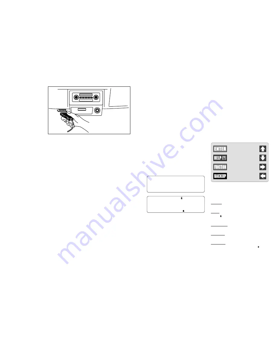
Insert the vehicle cable into
the scan tool receptacle and use the two
“thumb screws” to secure it to the connec-
tor as shown in the illustration below. Note
that you will feel a firm seating of the cable
as you secure it to the scan tool connector.
The vehicle cable adapter should always
be connected to the vehicle before power
is applied to the scan tool. This will enable
the scan tool to maintain a proper ground
between itself and the vehicle. If you have
connected to the vehicle, powered-up the
tool, and have difficulty establishing a link
between the scan tool and the vehicle,
check the following:
1. Is the ignition on?
2. Verify you have connected the vehicle
data cable to the vehicle’s Data Link
Connector (DLC).
3. Confirm that proper vehicle information
was entered into scan tool.
8
When attaching the data cable to the ve-
hicle, take time to review the specific ap-
plication manual for the cartridge you are
using. This will instruct you on correctly
connecting the cable to the vehicle. Many
of the vehicle adapters are “keyed” so that
the adapter will fit only one way. If you find
that you have a special vehicle situation or
the adapter does not fit, call 1-800-
ACTRON-7 for assistance. Always double
check the application section to be sure
that you are following the proper hook-up
directions. For further help that is not avail-
able in the scan tool help screens, see
Section 3: Actron Help for solutions to
your scan tool problems.
As you review the CP9110 Features sec-
tion on page 1-1 and 1-2, you will note
there is a complete view of accessory
vehicle adapter cables. They are for spe-
cial applications that only apply to certain
vehicles. If your vehicle is one of these,
you can order cables direct from Actron
by calling (800) 228-7667.
Connecting the
Vehicle Adapter Cable
9
1-6
Operating the Scan Tool
Powering-up the scan tool
The scan tool can be powered-up in three
ways. The most widely used way is with
the supplied cigarette lighter adapter. The
scan tool can also be powered up by using
the optional Battery Clip Adapter or 110/12V
AC Power Adapter. If you are powering-
up the scan tool for vehicle testing, then
make sure you connect the appropriate
cable to the data connector before you
supply power to the scan tool. If you do not
connect the vehicle data cable now, the
scan tool will let you know that you have not
connected the data cable. If you just want
to power-up the scan tool to do self-tests,
then you do not need to attach the cable
to the data connector.
When the scan tool powers-up, a series of
screens is displayed. The screens start
with a “Welcome” screen and end with a
“Key Button Help” screen.
Welcome To
The ScanTool
By Actron
Press HELP For Key
Button Information.
Press ENTER To Cont
Welcome & Key Button Help Screens
The screens in between the “Welcome”
and the “Key Button Help” screen are for
a tool self-test and the cartridge software
version. Refer to this software version if
you need to contact Actron’s technical
support line with a problem. If you wish to
review the key button definitions, then
push the HELP key; otherwise, press
ENTER to continue forward.
Keyboard
The scan tool software was designed for a
“user friendly” approach in navigating through
operational menus. This makes the scan tool
easy to operate. Simply follow the instructions
that match the keyboard symbols and you will
be using your scan tool like an expert in no time.
Since the keyboard is sealed, a damp cloth can
be used to gently clean the surface. (
Cau-
tion: DO NOT USE SOLVENTS LIKE
ALCOHOL! This could remove the
keyboard paint!)
Scan Tool Keyboard and Display
Keyboard Functions
The scan tool uses 8 keys to navigate
through the software-user interface:
ENTER
Used to enter or answer a
software request.
HELP
Used to request help when
the symbol is in the upper right hand
corner of the display.
FUNCTION Used to return user to
manufacturer’s function list.
BACKUP
Used to move one screen
back in scan tool flow.
ARROWS
UP or DOWN are always
used to move the solid cursor in the
direction of the arrow or scroll the data
list in the direction you want to move the
list
LEFT or RIGHT arrows move
the cursor in the direction of the arrow
and allow you to customize a vehicle
data parameter list.
UP
DOWN
RIGHT
LEFT


