


Display
The scan tool has a 4 line x 20 character
liquid crystal display (LCD) for easy view-
ing. This makes the scan tool “user friendly”
by offering a large viewing area to display
most Help and Instructional messages.
This also puts more information on the
display instead of referring you to printed
materials. Again the display will support a
number of helpful characters that will
prompt you through test routines. These
characters are shown below:
Question Mark in upper right corner
means there is help available for this
screen.
Bell in lower right corner means the
sound alert is on or active.
Cursor used to select menu choice.
Down Arrow indicates there is addi-
tional information on the next screen.
Up Arrow indicates there is additional
information on previous screen(s).
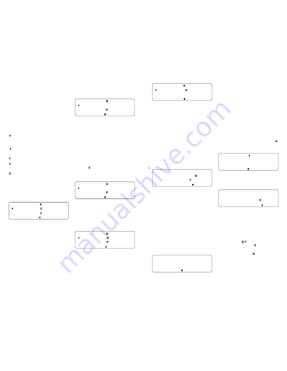
Below is a screen showing how these
symbols will look on your display (NOTE:
This is a GM Function List – Function Lists
for other manufacturers may differ slightly.):
GM Function List
4)Record Data
5)Playback Data
6)Field Service
Lists, Menus, and Questions
The scan tool is designed to be as intuitive
as possible. That is, its functions and con-
trols should be easy to understand and
use the first time you try it. All scan tool
menus and screen lists operate the same
way. By using the UP and DOWN arrow
keys, you can move the cursor to a menu
selection of your choice. The ENTER key
selects that function. Below is an example
of a Function List with several choices
10
(NOTE: This is a GM Function List –
Function Lists for other manufacturers
may differ slightly.):
GM Function List
1)Read Codes
2)Erase Codes
3)View Data
Note how the cursor is pointing at 1) Read
Codes. If you wish to read trouble codes,
press ENTER to select that function. To
make a different choice, such as viewing
data, use the DOWN arrow key to move
the cursor down next to 3) View Data and
press ENTER. This will select the View
Data function.
Sometimes, a list will be longer than three
or four items, and will not fit on a single
screen. In these cases, the down arrow
symbol ( ) is visible in the last column of
the display, indicating that there are more
choices on the next screen:
GM Function List
1)Read Codes
2)Erase Codes
3)View Data
To go to the next choice, use the DOWN
arrow key to move the cursor down the list.
NOTE: Pressing the DOWN arrow key
moves the function list one line at a time.
After several DOWN arrow key presses,
the screen below appears.
GM Function List
4)Record Data
5)Playback Data
6) Field Service
Now notice that there are arrows pointing
up and pointing down in the last column.
This indicates that you can use the UP
arrow key to move the cursor to the previ-
ous screen or press the DOWN arrow key
several times to move the cursor to the
third screen, shown below:
11
GM Function List
7)Beeper On-Off
8)English-Metric
9)Code Lookup
Notice now that there is only an arrow
pointing up in the last column. This indi-
cates that you have reached the end of this
list, and that all other choices are on
previous screens. You can return to those
screens by pressing the UP arrow key.
(NOTE: This is a GM Function List – Func-
tion Lists for other manufacturers may
differ slightly.).
These up and down arrow characters on
the screen are used throughout the scan
tool’s software. The UP and Down arrow
keys work exactly the same way, even if
you are just scrolling through text such as
the On-Line Help screen shown below:
3.TEST CONNECTOR:
DAMAGED/LOOSE PINS?
4.TOOL SETUP OK ?
CORRECT VINS,ETC?
Note that there are no choices to make
here, and that there is no cursor to move.
There are, however, up and down arrows
in the last column. These arrows indicate
that there are other screens before and
after this one. Using the UP and DOWN
arrow keys, you can scroll through the
entire message.
Occasionally, you may be asked a ques-
tion by the scan tool which requires a
response. These will always be YES or
NO questions, and are answered in al-
most the same way you make choices on
a Function List. Below is an example of a
YES/NO question:
View Instructions
For Creating Custom
Data List?
Yes <No>
In these screens, brackets will automati-
cally be next to the default response. If you
wish to accept the default choice, simply
press ENTER. If you wish to change the
answer, use the LEFT or RIGHT arrow key
to move the brackets next to the other
response and press ENTER.
Other Functions & Keys
As you have reviewed moving through
lists and functions in earlier sections, you
probably noticed several other symbols
on the screen. In the upper right-hand
corner of some screens, there is a large .
This question mark indicates that On-Line
Help is available for that particular screen:
Operating Error.
Check Connections!
Try Again?
<Yes> No
To enter On-Line Help, press the HELP
key. For the screen above, the help mes-
sage would look like this:
RECHECK FOLLOWING:
1.IGNITION KEY ON?
2.HOOKUP TO VEHICLE
TEST CONNECTOR OK?
All On-Line Help screens have their text
typed in ALL CAPITAL LETTERS. This is
another reminder that you are viewing On-
Line Help screens and not screens asso-
ciated with a function of the Function List.
Some On-Line Help messages are longer
than one screen. If this is the case, the
arrow symbols (
) will appear in the last
column of the display. A means there is
more On-Line Help information available
on the next screen. A means there is
more On-Line Help information available
on the previous screen. Use the UP and
DOWN arrow keys to page up or down
through a series of On-Line Help screens.


