


User Manual of Network Camera
45
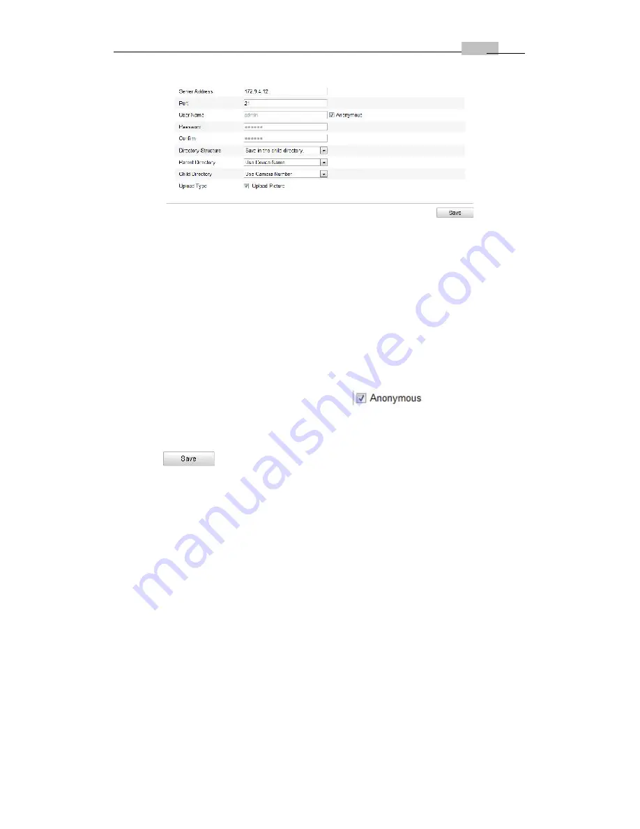
Figure 6-15
FTP Settings
2. Configure the FTP settings; and the user name and password are required for
login the FTP server.
Directory
: In the
Directory Structure
field, you can select the root directory,
parent directory and child directory. When the parent directory is selected, you
have the option to use the Device Name, Device Number or Device IP for the
name of the directory; and when the Child Directory is selected, you can use the
Camera Name or Camera No. as the name of the directory.
Upload type:
To enable uploading the captured picture to the FTP server.
Anonymous Access to the FTP Server (in which case the user name and
password won’t be requested.):
Check the
checkbox to enable
the anonymous access to the FTP server.
Note:
The anonymous access function must be supported by the FTP server.
3. Click
to save the settings.
Notes:
If you want to upload the captured pictures to FTP server, you have to
enable the continuous snapshot or event-triggered snapshot on
Snapshot
page.
For detailed information, please refer to the
Section 6.6.8.
6.3.9 Configuring UPnP™ Settings
Universal Plug and Play (UPnP™) is a networking architecture that provides
compatibility among networking equipment, software and other hardware devices.
The UPnP protocol allows devices to connect seamlessly and to simplify the
implementation of networks in the home and corporate environments.
With the function enabled, you don’t need to configure the port mapping for each
port, and the camera is connected to the Wide Area Network via the router.
Steps:
1. Enter the UPnP™ settings interface.
Configuration >Advanced Configuration > Network > UPnP
2. Check the checkbox to enable the UPnP™ function.
The name of the device when detected online can be edited.


