background image

actiLib  Autoloader 1U – Quick Start Guide


Page 4 of 17 


  Unauthorized modifications to the unit configuration by the customer may result in loss of 

guarantee by the vendor. 

Rack stability 


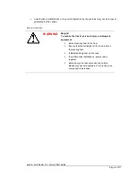
WARNING 

Weight! 
To reduce the risk of personal injury or damage to 
equipment  

  Extend leveling feet to the floor. 

  Ensure that the full weight of the rack rests on 

the leveling feet. 

  Install stabilizing feet on the rack. 

  In multiple-rack installations, secure racks 

together. 

  Extend only one rack component at a time. 

Racks may become unstable if   more than one 
component is extended 

Summary of Contents for actiLib Autoloader 1U

Page 1: ...actiLib Autoloader 1U Quick Start Guide Page 1 of 17 actiLib Autoloader 1U Quick Start Guide September 2009 ...

Page 2: ...g the tape loader 7 4 Front panel 10 4 1 Rear panel 11 5 Labeling tape cartridges 13 6 Magazines 14 6 1 Inserting tape cartridges into a magazine 14 6 2 Removing and replacing a magazine using the OCP 14 6 3 Slot numbering 15 6 4 Mailslot 15 7 Connecting the Library 16 7 1 SCSI installation 16 7 2 SAS installation 16 7 3 Fibre channel installation 16 7 4 Configuring the library 16 8 Power ON OFF t...

Page 3: ...evel surface free from vibration Do not place anything on top of the unit that weighs more than 15 kg Product warranty Caution The warranty for the tape loader shall not apply to failures of any unit when The tape loader is repaired or modified by anyone other than the manufactures personnel or approved agent The tape loader is physically abused or used in a manner that is inconsistent with the op...

Page 4: ...ility WARNING Weight To reduce the risk of personal injury or damage to equipment Extend leveling feet to the floor Ensure that the full weight of the rack rests on the leveling feet Install stabilizing feet on the rack In multiple rack installations secure racks together Extend only one rack component at a time Racks may become unstable if more than one component is extended ...

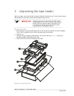
Page 5: ...e loader was stored allow the loader to acclimate to the surrounding environment for at least 12 hours before unpacking it from the shipping container Unpacking the loader 1 Before opening and removing the loader from the box inspect the container for shipping damage If you notice any damage report it to the shipping company immediately 2 Open the box 3 Carefully remove the shipping materials from...

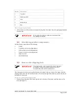
Page 6: ...ations SCSI cable not in all configurations Power cord not in all configurations Rack mount kit Quick Start Guide 3 2 Remove the shipping lock IMPORTANT The shipping lock which prevents the robotic transport mechanism from moving during shipment must be removed before the loader is powered on The shipping lock is held in place with a label and is located in the top center of the loader After the s...

Page 7: ...der always remove all tapes to reduce the overall weight of the loader observe local health and safety requirements and guidelines for manual material handling Required tools 3 Phillips screwdriver T10 Torx screwdriver There are two sets of eight M6 screws in the accessory package that came with your loader The type of rack that you have will determine the type of M6 screw that you will use To ins...

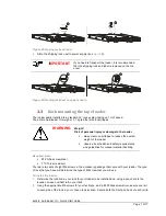
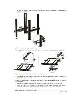
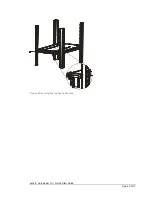
Page 8: ...g brackets and guide pulleys 2 Install the loader guide pulleys on each side of the loader using the 2 Torx screws included in the rack kit see Figure 5 step 2 Install the mounting brackets of the loader using the 4 Torxs screws included in the rack kit Shown in Figure 5 step 3 3 With loader guide pulleys and mounting brackets installed slide the loader onto the rails 4 Secure the loader to the ra...

Page 9: ...actiLib Autoloader 1U Quick Start Guide Page 9 of 17 Figure 6 Securing the loader to the rack ...

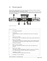
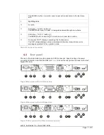
Page 10: ...l initiate a controlled Power Down of the unit soft power down 3 LED READY Green Illuminated when power is on Blinking when there is tape or loader robotics activity 4 LED CLEAN Amber Illuminated when the tape drive has determined that a cleaning cartridge should be used Cleaning is only necessary when the loader directs you to do so Additional cleaning is not necessary 5 LED ATTENTION Amber Illum...

Page 11: ...13 Front panel OCP display consisting of 2x16 characters The OCP screen displays actions and status information menu items or error messages equivalent to the operation mode Table 2 Front panel overview 4 1 Rear panel The rear of the tape loader provides access to SCSI connectors tape drive bays the power connector Ethernet serial and the USB port Figure 8 show the rear panel of a loader with a ha...

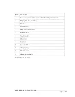
Page 12: ...uires a 110 220 volt AC power connection 2 Shipping lock storage location 3 Fan vent 4 Tape drive sled 5 68 pin HD SCSI connectors 6 Product label foil 7 Tape Drive LED 8 Ethernet port 9 Serial port 10 Controller LED 11 USB port Host 12 SAS connectors 13 Fibre channel connectors Table 3 Rear panel overview ...

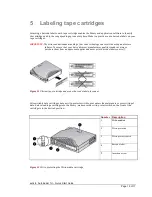
Page 13: ... that your bar codes meet manufactures quality standards always purchase them from an approved supplier and never print bar code labels your self Figure 11 Ultrium tape cartridge and proper bar code label placement All rewritable data cartridges have a write protect switch to prevent accidental erasure or overwriting of data Before loading a cartridge into the library make sure the write protect s...

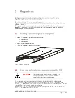
Page 14: ...e 1 Unlock the magazines and remove it from the loader Use the OCP Use the RMU 2 Insert cartridge in the magazines 3 Put the full magazines back to the tape loader Figure 13 Insert magazines 6 2 Removing and replacing a magazine using the OCP CAUTION The magazine must only be removed manually in an emergency Failure to follow normal procedure can cause data loss and equipment damage The magazines ...

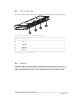
Page 15: ...ail slot Number Description 1 Mail slot 2 LTO Slot 3 LTO Slot 4 LTO Slot Table 4 Slot numbering left magazine 6 4 Mailslot Mailslots are used to import export individual cartridges without interrupting library operation The command to open the mailslot may be denied if the robotics is busy with some operation In that case Busy is displayed and the command has to be repeated once the robotics opera...

Page 16: ...uld NOT exceed 9 meters 30 feet 7 2 SAS installation If your loader includes tape drives with SAS interface connect SAS cables to the tape drives Attach one end of the SAS cable to the SAS port on the unit and the other end of the cable to the host 7 3 Fibre channel installation If your loader includes fibre channel tape drives connect fibre cables to the unit and the other end of the cable to the...

Page 17: ...re the unit shuts down completely The display indicates with an appropriate message that the shutdown is in progress The library controller finishes all ongoing loader and drive activities The robotics is moved to its home position The library controller switches off the power supply s secondary side To abort the shutdown process the user has to press Cancel within the first 3 seconds Note The shu...

Reviews: