background image

www.acti.com

Installation Guide 


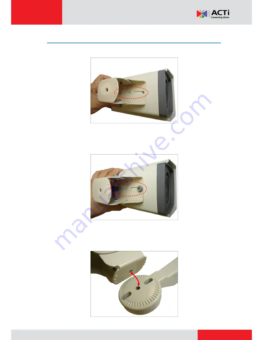
  Step 5: Install the Camera 

1.


Align the screw holes of the holder to the bottom screw holes of the camera. 


2.


Attach the two (2) screws (supplied in the bracket package) to secure the camera to the 

holder. 


3.


Align the screw hole of the holder to the bracket as you insert the excess length of flex 

conduit back into the pole mount. 


Summary of Contents for KCM-5*11E

Page 1: ...2013 12 06 Outdoor Ready Box Mounting on a Straight Wall using the Bracket Installation Guide For Models KCM 5511 KCM 5611 KCM 5x11E...

Page 2: ...2 Remove the Back Cover 4 Step 3 Prepare the Flex Conduit 4 Step 4 Connect the Ethernet Cable 7 Step 5 Install the Camera 8 Step 7 Access the Camera Live View 10 Appendices 11 Connecting a Power Adapt...

Page 3: ...re the following tools and accessories which are not included in the camera package thus must be purchased separately Bracket PMAX 1101 Flexible Conduit Trade size 1 2 Ethernet Cable Screwdriver Step...

Page 4: ...Prepare the Flex Conduit 1 From the network side insert the Ethernet cable and other cables if any through the flex conduit NOTE To connect an external power adaptor digital input output DI DO or seri...

Page 5: ...rt the clamping nut through the flex conduit 3 Insert the sealing insert and attach it at the end of the flex conduit 4 Detach the conduit gland from the back cover of the camera as shown below Sealin...

Page 6: ...ough the conduit gland body of the back cover Ethernet Cable Only Ethernet and Power Adaptor Cable 6 Insert the sealing insert into the conduit gland body 7 Attach the clamping nut to complete the cab...

Page 7: ...power adaptor DI DO or serial devices connect the supplied terminal blocks and connect them to the corresponding connectors of the camera see Appendices on page 11 for more information Sample image be...

Page 8: ...holes of the holder to the bottom screw holes of the camera 2 Attach the two 2 screws supplied in the bracket package to secure the camera to the holder 3 Align the screw hole of the holder to the bra...

Page 9: ...eded turn the holder left or right to adjust the camera viewing direction Then secure the screw tightly to fix the position 6 As needed loosen the two 2 side screws of the holder and then move the cam...

Page 10: ...ss the Camera Live View Connect the other end of the Ethernet cable to a PoE switch and access the camera live view For more information on how to access the camera Live View download the camera Hardw...

Page 11: ...f these devices however is optional Connecting a Power Adaptor Optional In case of using a non PoE switch or your PoE switch has limited power supply you can purchase a power adaptor and directly conn...

Page 12: ...and the other to the GND pin 4 Tighten the screws of the 12V pin and the GND pins to secure the wire connection 5 Set the prepared power adaptor for connection later Below is an example of a power ad...

Page 13: ...e activated by the camera upon an event inside the camera For example you can connect an alarm horn to the camera as such when an event occurs inside the camera e g detected intruder the alarm horn wi...

Page 14: ...low Logic level 0 0V 0 4V Normal high Logic level 1 3 1V 30V Current 10mA 100mA DO Connection design Transistor Open Collector Voltage Current 24V DC 100mA Typical Connection Based on these specifica...

Page 15: ...ons and make sure they match the above design The triggering circuit voltage has to be around 12V DC and the switch controlled circuit voltage has to match the external power supply e g 110V AC or 220...

Page 16: ...rom the PT scanner to your camera using the supplied terminal block according to one of the tables below Via RS 485 Connection Terminal Block Wire Mapping Pin Number Label Camera Pin PT Scanner Pin 1...

Page 17: ...er wiring 2 Connect a ground wire to one of the GND terminal pins of your camera via Power or DI O terminals to complete the connection For more information on connecting PT scanners please refer to t...

Page 18: ...care has been taken during the writing of this manual Please inform your local office if you find any inaccuracies or omissions We cannot be held responsible for any typographical or technical errors...

Page 19: ...ctly exposed to rain or water 4 If the video product does not operate normally by following the operating Instructions in this manual Adjust only those controls that are covered by the instruction man...

Reviews: