background image

www.acti.com

Hardware Manual 


42 

Accessing the Camera 

Configure the IP Addresses 

In order to be able to communicate with the camera from your PC, both the camera and the PC 

have to be within the same network segment. In most cases, it means that they both should have 

very  similar  IP  addresses,  where  only  the  last  number  of  the  IP  address  is  different  from  each 

other. There are 2 different approaches to IP Address management in Local Area Networks 

– by 

DHCP Server or Manually. 


Using DHCP server to assign IP addresses 

If  you  have  connected  the  computer  and  the  camera  into  the  network  that  has  a  DHCP  server 

running, then you do not need to configure the IP addresses at all 

– both the camera and the PC 

would  request  a  unique  IP  address  from  the  DHCP  server  automatically.  In  such  case,  the 

camera will immediately be ready for the access from the PC. The user, however, might not know 

the IP address of the camera yet. It is necessary to know the IP address of the camera in order to 

access it using a Web browser. 


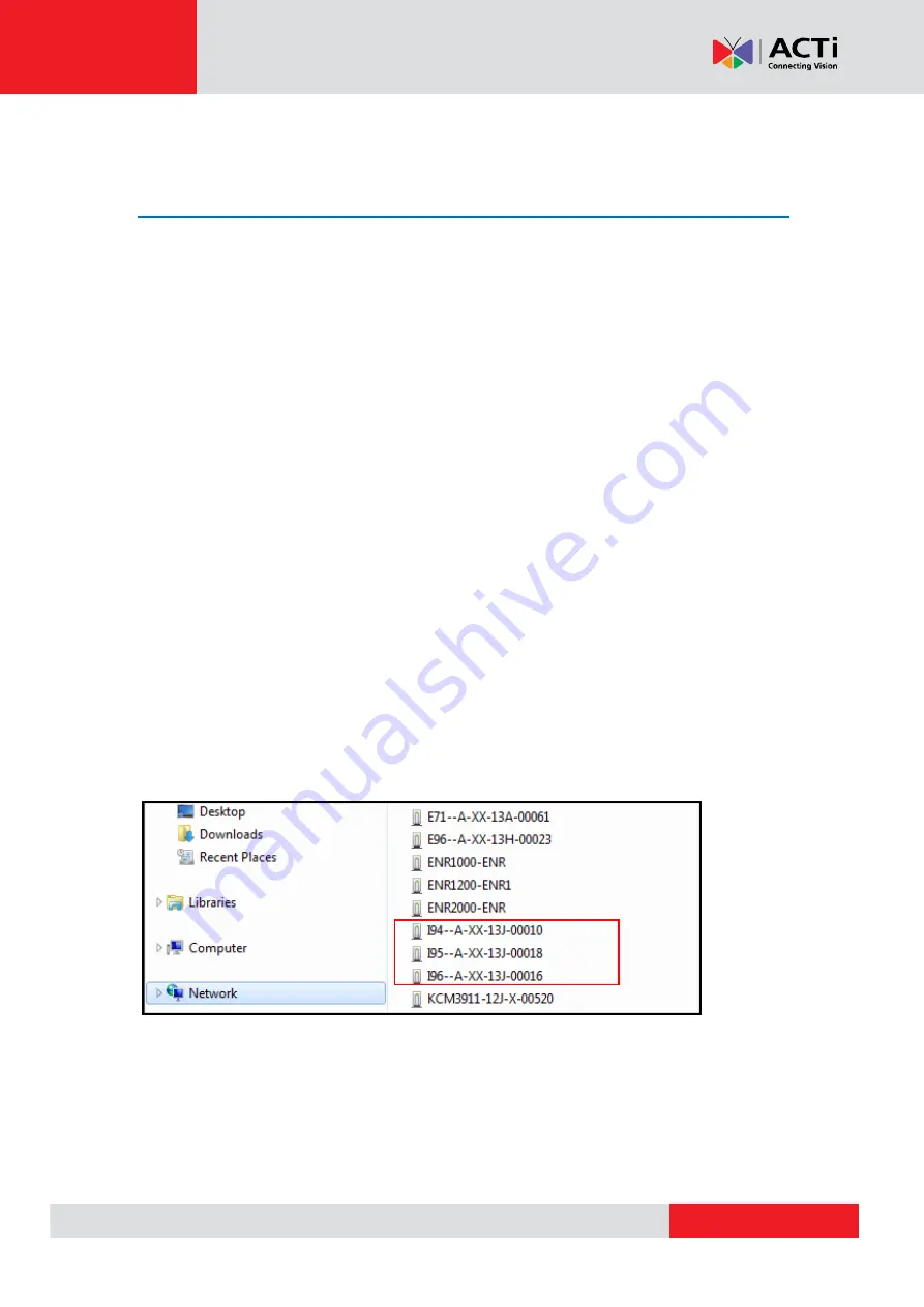
The  quickest  way  to  discover  the  cameras  in  the  network

  is  to  use  the  simplest  network 

search, built in the Windows system 

– just by pressing the “Network” icon, all the cameras of the 

local  area  network  will  be  discovered  by Windows,  thanks  to the  UPnP  function  support  of  our 

cameras. 

In  the  example  below,  the  camera  model  that  has  just  been  connected  to  the  network  is 

successfully found. 


Double-click  the  mouse  on  the  camera  model  name,  the  default  browser  of  the  PC  is 

automatically  launched and the IP  address of the target camera is already  filled in the address 

bar of the browser. 


Summary of Contents for I93

Page 1: ...Outdoor PTZ Speed Dome Camera Hardware Manual B916 B917 I93 I94 I95 I96 I97 I910 2016 06 20...

Page 2: ...12 Before Installation 13 Unpack the Camera 13 Attach the Safety Strap 15 Installation Procedures 16 Mount the Camera 16 Waterproof the Cable Connections 18 How to Waterproof the Cable Using the Cabl...

Page 3: ...evices 31 How to Connect Audio Devices 36 Other Accessories 37 How to Install the Memory Card 37 How to Remove the Memory Card 37 How to Attach the Safety Wire Strap 38 How to Replace the Dome Cover 4...

Page 4: ...attempt to service this video device yourself as opening or removing covers may expose you to dangerous voltage or other hazards Refer all servicing to qualified service personnel Trademarks All names...

Page 5: ...urning the equipment off and on the user is encouraged to try to correct the interference by one or more of the following measures Reorient or relocate the receiving antenna Increase the separation be...

Page 6: ...to qualified service personnel under the following conditions 1 When the power supply cord or plug is damaged 2 If liquid has been spilled or objects have fallen into the video product 3 If the inner...

Page 7: ...D N Extreme WDR SLLS 30x Zoom lens I93 1MP Outdoor PTZ with D N Extreme WDR ELLS 30x Zoom lens I94 2MP Outdoor PTZ with D N Extreme WDR ELLS 30x Zoom lens I95 1MP Outdoor Speed Dome with D N Extreme...

Page 8: ...contact your local sales agents or the Customer Help Desk CHD Camera Power Cord Power Adapter Universal Converter Cable Gland Conduit Gland Gland Rubber Rings x2 Hex Screwdriver Safety Strap Screws Qu...

Page 9: ...iver to remove the cover b Press and hold the reset button for at least 5 seconds or until the Power LED goes off 2 Memory Card Slot Insert a memory card into this slot for local recording purposes Se...

Page 10: ...Input Output The two 2 connectors connect to digital input or output devices such as an alarm trigger panic button etc Digital Input DI and Digital Output DO devices are used for applications like mo...

Page 11: ...it our website http www acti com mountingselector Mount Types Accessories Pendant Mount Suitable when mounting the Outdoor PTZ on a hard ceiling PMAX 0102 Straight Tube w o Bracket PMAX 0103 Straight...

Page 12: ...uitable when mounting the Outdoor PTZ on a horizontal pole PMAX 0102 PMAX 0503 Corner Mount Suitable when mounting the Outdoor PTZ on a corner wall PMAX 0312 PMAX 0402 Other Mounting Accessories Acces...

Page 13: ...until the camera is completely installed However the plastic has been removed on the pictures in this documentation to show clarity of the procedures being described 1 Loosen the four 4 screws using t...

Page 14: ...3 Remove the styrofoam and silicon bags from the camera 4 If a memory card will be used for local recording insert the memory card at this point 5 Align the screw holes and tightly secure the screws u...

Page 15: ...g accessory prior to continuing with installation 1 Locate and remove the set screw on the top of the camera 2 Insert the removed set screw to the smaller hole of the safety strap 3 Attach the set scr...

Page 16: ...access behind the wall For detailed information and other mounting solutions download the Installation Guide from the website http www acti com mountingselector NOTE The following pictures are for ref...

Page 17: ...ns on page 18 DISCLAIMER ACTi will not be responsible for camera damage caused by water entering the cable connections 3 Mount the camera 1 Align the gap on the camera to the tab inside the mounting s...

Page 18: ...he camera comes with a Cable Gland and Conduit Gland It is recommended to use one of these glands when a high PoE injector will be used with the camera However if the bundled power adapter will be use...

Page 19: ...following items Cable Gland Exterior Grade Ethernet Cable Waterproof Tape NOTE Not included in the camera package NOTE Not included in the camera package 2 Detach the cable gland as shown below 3 Ins...

Page 20: ...ubber ring is attached on the gland body smooth end NOTE Make sure the rubber ring is completely aligned on the gap on the gland body 6 Attach the gland body to the Ethernet port of the camera IMPORTA...

Page 21: ...onnector to the Ethernet port of the camera 8 Insert the sealing rubber and claw into the cable gland body 9 Attach the clamping nut to the cable gland body Make sure the clamping nut is tightly secur...

Page 22: ...cable connections or arrange all unused cables and wrap them with the waterproof tape NOTE Different applications and installation environments require different types of waterproofing methods which...

Page 23: ...t Gland 1 2 Flexible Conduit Waterproof Tape NOTE Not included in the camera package NOTE Not included in the camera package 2 Detach the conduit gland as shown below 3 Insert the Ethernet cable throu...

Page 24: ...e the rubber ring is attached on the gland body smooth end NOTE Make sure the rubber ring is completely aligned on the gap on the gland body 6 Attach the gland body to the Ethernet port of the camera...

Page 25: ...ect the Ethernet connector to the Ethernet port of the camera 8 Insert the sealing rubber into the conduit gland body 9 Attach the clamping nut to the conduit gland body Make sure the clamping nut is...

Page 26: ...thods to cable connections or arrange all unused cables and wrap them with the waterproof tape NOTE Different applications and installation environments require different types of waterproofing method...

Page 27: ...ion box 2 From the network power source side insert the cables such as the Ethernet cable through a 1 2 flexible conduit the flex conduit is not included in the package and through one of the holes of...

Page 28: ...et Cable Data Power Ethernet Cable Data Camera The Power LED of the camera will flash a few times and turn off as the camera mechanical components initialize Wait for the initialization to complete On...

Page 29: ...as alarms sensors etc and Audio Input and Output devices The use of these devices however is optional How to Use the Power Adapter 1 Slide the voltage switch to set the adapter voltage according to t...

Page 30: ...switching the wrong power voltage a replacement fuse is already included Follow the procedures below to replace the fuse 1 Use a flat head object such as a screwdriver to pull and remove the fuse hol...

Page 31: ...rs of events For example you can connect a panic button to the camera as such when the panic button is pressed the alarm signal will be sent through the camera Other common DI device applications are...

Page 32: ...n GND To connect digital input devices map the DI device wires to the following Digital Input 1 DI1 DI1 and GND Digital Input 2 DI2 DI2 and GND Digital Input 3 DI3 DI3 and GND Digital Input 4 DI4 DI4...

Page 33: ...nnection design Transistor Open Collector Voltage Current 24V DC 50mA Based on these specifications if the DI device has a voltage of 0V 30V or the DO device has a voltage of 24V 50mA then the camera...

Page 34: ...ection Even though the camera provides 12V power this may not be enough for some high voltage DO devices such as a ceiling light or a motor that opens or closes a gate In this case there is a need to...

Page 35: ...cting a relay to a high voltage DO device Relay DO1 Device Outdoor PTZ Illuminator 110V 220V AC External Power Source NOTE For more information on DI DO connections please refer to the article All Abo...

Page 36: ...tput jack GREEN jack of the camera If the camera is installed outdoors be sure o wrap the audio connectors with Waterproof tape can be purchased in hardware stores DISCLAIMER ACTi will not be responsi...

Page 37: ...te the memory card slot on the camera 2 Insert the memory card into the memory card slot with the metallic contacts facing the camera 3 Push the card until it clicks into place 4 Close the camera cove...

Page 38: ...nal protection to avoid dropping the camera while mounted on the high ceilings etc To attach the safety wire strap do the following 1 Using a screwdriver remove the screw on top of the camera 2 Insert...

Page 39: ...www acti com Hardware Manual 39 4 Align the bigger end of the safety wire strap on the mounting solution and then tightly attach the screw to lock the safety wire strap in place...

Page 40: ...arent or smoke Vandal Proof IK10 dome cover available for purchase To replace the dome cover do the following 1 Loosen the four 4 screws using the hex screwdriver included in the camera package 2 Care...

Page 41: ...www acti com Hardware Manual 41 4 Attach the dome cover to the camera by securing the screw through the wire strap 5 Tighten the four 4 screws to close the dome cover...

Page 42: ...he PC would request a unique IP address from the DHCP server automatically In such case the camera will immediately be ready for the access from the PC The user however might not know the IP address o...

Page 43: ...serial numbers firmware versions etc and allows quick configuration of multiple devices at the same time Search and downloand IP Utility for free from http www acti com DownloadCenter When you launch...

Page 44: ...o the network and it does not detect any DHCP services it will automatically assign itself a default IP 192 168 0 100 Whereas the default port number would be 80 In order to access that camera the IP...

Page 45: ...IP Utility With the procedure shown above all the cameras will have unique IP addresses starting from 192 168 0 101 In case there are 20 cameras selected the last one of the cameras would have the IP...

Page 46: ...Explorer browsers free third party software plug ins must be installed to the PC first to be able to get the live video feed from the camera Browser Required Plug In Safari QuickTime http www apple co...

Page 47: ...s address bar http 192 168 0 100 Upon successful connection to the camera the user interface called Web Configurator would appear together with the login page The HTTP port number was not added behin...

Page 48: ...Copyright 2015 ACTi Corporation All Rights Reserved 7F No 1 Alley 20 Lane 407 Sec 2 Ti Ding Blvd Neihu District Taipei Taiwan 114 R O C TEL 886 2 2656 2588 FAX 886 2 2656 2599 Email sales acti com...

Reviews: