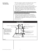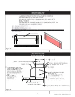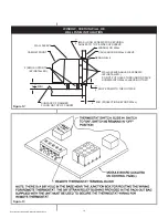
Suburban Dynaline 3 A&E Manual 12/2021 Rev.2
12
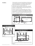
HEADER
(STEEL LINTEL IN BRICK CONSTRUCTION)
FINISHED FLOOR
SUB-FLOOR
NOTE: UNITS APPROVED FOR 0" CLEARANCE TO COMBUSTIBLE CONSTUCTIONS TOP, SIDES, AND BOTTOM. FRONT AND REAR CLEARANCE
NOT APPLICABLE AS THERE CAN BE NO CONSTRUCTION COMBUSTIBLE OR NON-COMBUSTIBLE TO THE FRONT OR REAR OF THE OPENING.
42
1
—
4
" MIN.
16
1
—
4
" MIN.
3
1
—
2
" MIN.
FRAMING
In the United States and Canada, the installation must conform with local
codes. In the absence of local codes, US installations must conform with
the current National Fuel Gas Code ANSI Z223.1 and with the National
Electrical Code ANSI/NFPA No. 70, and Canadian installations must
conform with the current CANI-B149 installation code.
After selecting a location, inspect the wall and floor areas to determine
that there are no hidden electrical wires, piping, tubing, ducts, girders,
wall studs, etc., that might interfere with the proper installation and safe
operation of the unit and gas supply.
Dynaline
™
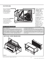
3 is designed to be installed through an exterior wall from
1" to 14-1/2" thick. To accommodate the unit’s dimensions (see
Figure 5
),
the wall opening must be framed as shown in
Figures 6 & 7
. For walls
thicker than 14-1/2", consult factory regarding available extended length
wall sleeves. The maximum wall thickness for rear gas hook-up is 12-5/8".
NOTE: Use conventional construction methods to frame the opening.
Do not use the wall sleeve as a lintel.
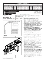
Figure 5
Figure 7
UNIT OVERALL DIMENSIONS
WALL SLEEVE FRAMING DIMENSIONS
FRONT GAS HOOK-UP
MIN.
1—
4
MIN.
HEADER
(STEEL LINTEL IN BRICK CONSTRUCTION)
SURFACE OF FINISHED FLOOR
42
1—
4
"
16 "
Figure 6
WALL SLEEVE FRAMING DIMENSIONS
REAR GAS HOOK-UP


