


AR-B1579 User
’
s Guide
3-10
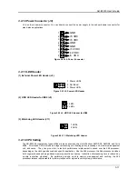
3.2.9 PS/2 Mouse Connector
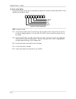
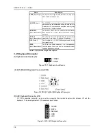
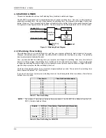
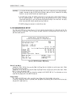
(1) PS/2 Mouse IRQ12 Setting (JP3)
The default of <Enabled> allows the system detecting a PS/2 mouse on boot. If detected, IRQ12 will be used for
the PS/2 mouse. IRQ12 will be reserved for expansion cards and therefore the PS/2 mouse will not function.
Enable
Factory Preset
1
2
1
2
Disable
JP3
Figure 3-18 JP3: PS/2 Mouse IRQ12 Setting
CAUTION:
After adjusting the JP2 correctly, the user must set the <PS/2 Mouse Support> option to Enabled in the
BIOS <Advanced CMOS Setup> Menu. Then the PS/2 mouse can be used.
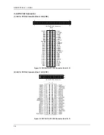
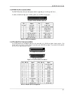
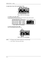
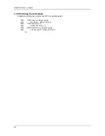
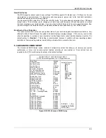
(2) PS/2 Mouse Connector (CN5 & J6)
To use the PS/2 interface, an adapter cable has to be connected to the J6 (6-pin header type) connector. This
adapter cable is mounted on a bracket and is included in your AR-B1579 package. The connector for the PS/2
mouse is a Mini-DIN 6-pin connector. Pin assignments for the PS/2 port connector are as follows:
Figure 3-19 CN5 & J6: PS/2 Mouse Connector
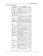
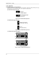
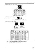
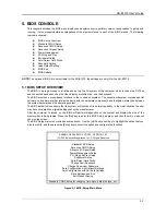
3.2.10 External Speaker Header (J1)
Besides the onboard buzzer, you can use an external speaker by connecting to the J1 header.
1
2 Speaker-
3 Speaker-
4 Speaker-
Figure 3-20 J1: Speaker Header
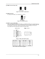
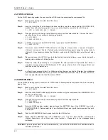
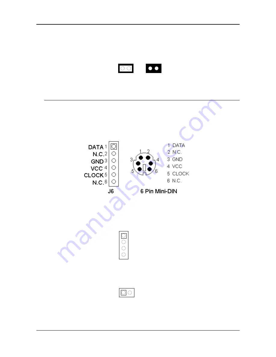
3.2.11 Reset Header (J8)
J8 is used to connect to an external reset switch. Shorting these two pins will reset the system.
1 Reset+
1
2
2 Reset-
Figure 3-21 J8: Reset Header