


AR-B1579 User's Guide
3-3
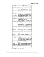
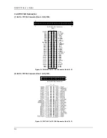
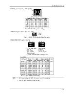
3.2.3 Hard Disk (IDE) Connector
40-Pin Hard Disk (IDE) Connector (CN1)
A 40-pin header type connector (CN1) is provided to interface with up to two embedded hard disk drives (IDE AT
bus). This interface, through a 40-pin cable, allows the user to connect up to two drives in a “daisy chain” fashion.
To enable or disable the hard disk controller, please use the BIOS Setup program. The following table illustrates
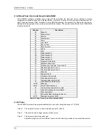
the pin assignments of the hard disk drive’s 40-pin connector.
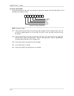
1
2
40
39
Figure 3-4 CN1: Hard Disk (IDE) Connector
Pin Signal Pin Signal
1 -RESET 2 GROUND
3 DATA
7 4 DATA
8
5 DATA
6 6 DATA
9
7
DATA 5
8
DATA 10
9
DATA 4
10
DATA 11
11
DATA 3
12
DATA 12
13
DATA 2
14
DATA 13
15
DATA 1
16
DATA 14
17
DATA 0
18
DATA 15
19 GROUND 20 NOT
USED
21 IDEDRQA 22 GROUND
23 -IOW
A 24
GROUND
25 -IOR
A 26
GROUND
27 -CHRDY
A 28 GROUND
29 DACKA 30
GROUND
31
-IRQ 14
32
NOT USED
33
SA 1
34
NOT USED
35 SA
0 36 SA
2
37 CS
0 38 CS
1
39
HD LED A
40
NOT USED
Table 3-1 CN1: Hard Disk (IDE) Connector