6
6
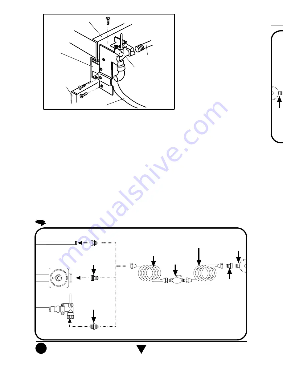
- Retire la válvula de seguridad desconectando el tubo de gas mostrado en la figura (según
modelo). El refuerzo lateral debe ser atornillado con el lateral de la estufa, use el tornillo
que se provee en el kit de conversión.
- Deslice la estufa sobre los canales laterales sin llegar al fondo del mueble.
- Coloque nuevamente la válvula de seguridad en la posición que muestra la figura superior
y conecte nuevamente el tubo de gas.
- Conecte la estufa como se muestra en la figura inferior y verifique con agua jabonosa
que no haya fugas de gas.
- Realice cuidadosamente las conexiones eléctricas necesarias.
- Deslice la estufa hasta el fondo del mueble.
- Reemplace los tubos
venturi
por los tubos más largos que se proveen con la estufa.
- Coloque nuevamente los cables de las bujías.
- Ensamble la cubierta superior primero de un lado para enganchar los clips y luego el otro.
- Ensamble los tornillos correspondientes de la cubierta superior, estos deberan sujetar
al tubo venturi.
- Coloque los quemadores superiores, tapas de quemadores y en su caso, el capelo de
cristal.
- Verifique que la válvula de seguridad funcione correctamente como se menciona en la
página 11.
- Disconnect the gas tube from the shut off valve to remove it (According to the model).
Screw the side bracket to the body side with the screw provided in the conversion kit.
- Slide the range on the side channels allowing a space between the range and the back
of the countertop.
- Connect again the gas tube to the shut off valve to relocate it as shown in the figure at
the top.
- Connect the range to the gas supply as shown in the figure at the bottom and verify that
there are no gas leaks using soap solution.
- Connect the electrical power cord.
- Slide the range to the back of the countertop.
- Replace the venturi tubes with the longer tubes provided in the range.
- Connect the spark plugs wires.
- Assembly the cooktop moving it from one side to fix the clips and then fix the other side.
- Screw the venturi tubes to the cooktop.
- Replace the burners and caps, and the glass lid if your range has it.
- Verify that the shut of
f valve is assembled to function as indicated in page 11.
CONEXIÓN DE LA ESTUFA A LA LÍNEA DE GAS
GAS SUPPLY CONNECTION
NOTA: El material mostrado para instalacion no viene con la estufa.
NOTA: Su estufa puede estar equipada de fábrica con:
1.- Tubo de Alimentacion ó
2.- Regulador de Gas ó
3.- Válvula de Corte de Gas.
Tubo de Alimentación
integrado a la estufa
Llave de paso
de 9,5 mm (3/8")
Cople-Niple de 9,5 mm (3/8"NPT)
a 9,5 mm(3/8")cónica
Tubo de cobre con tuercas
cónicas de 9,5 mm (3/8")
Tubo de cobre con tuercas
cónicas de 9,5 mm (3/8") de
longitud necesaria para llegar
al gas
Cople-Niple de
9,5 mm (3/8"NPT)
Regulador
de gas
Niple de 12,7 mm (1/2")NPT
a 9,5 mm(3/8")cónica
Regulador de Gas
integrado a la estufa
Válvula de Corte de
Gas
integrado a la
estufa
Niple de 9,5 mm(3/8"NPT)
a (3/8")cónica
NOTE: The material shown for installation is not provided with the
range.
NOTE: The range could be equipped from the factory with
one of the following accesories:
1.- Gas Inlet Tube Fitting or
2.- Gas Regulator or
3.- Shut Off Gas V
alve.
3/8" shut off
valve
Gas Inlet Tube Fitting
integrated to the range
3/8" NPT to 3/8" brass pipe
fitting Hex. adapter
3/8" copper
pipe
with 5/8" flared
type nut
Gas
regulator
3/8" copper pipe with
5/8" flared type nut.
Necessary
length to reach the
gas
3/8" brass pipe
fitting
Hex. adapter
Gas Regulador
integrated to the
range
Shut Off Gas
Valve
integrated to the
range
1/2" NPT to 3/8" brass
pipe fitting Hex. adapter
3/8" NPT to 3/8" brass
pipe fitting Hex. adapter
CANAL LATERAL SOBRE
LA CUBIERTA DE LA COCINA
REFUERZO
LATERAL
RESPALDO DE LA ESTUFA
VÁLVULA DE SEGURIDAD
Posición de la válvula de seguridad para montaje de la estufa tipo Drop In.
SIDE CHANNEL IN THE
KITCHEN COUNTERTOP
SIDE BRACKET
MAIN BACK
SHUT OFF VALVE
Shut off valve position to install the range as Drop In.
TUBO DE GAS
GAS TUBE
CUBIERTA DE
LA COCINA
KITCHEN
COUNTERTOP
LATERAL DE
LA ESTUFA
BODY
SIDE
Summary of Contents for ACK2400
Page 4: ...4 ...
Page 8: ...8 ...
Page 10: ...10 r ...
Page 12: ...12 A lu p A la ti y d 1 2 3 A S a in L p p A n L la s p ...
Page 14: ...14 Ase est Abr Cie pas No Apa Lla aut No oca exp Interrup Termos Relev ...
Page 16: ...16 So ...


