background image

13

Limpieza

Es necesaria la limpieza periódica de la estufa, use agua, jabón y un trapo húmedo, no

use fibra metálica, porque se ralla el esmalte. Limpie regularmente el hueco entre la

cubierta superior y el frente de perillas.

Su estufa cuenta con el 

Sistema de Autolimpieza

 en el horno (acabado rugoso), no es

necesario que 

limpie las 

paredes, ya 

que con 

cada horneado 

se van 

quemando los 

residuos

de alimentos que se van salpicando.

    • Como retirar la charola del horno:

    1.- Tome la charola de las ranuras laterales.

         y levántela de la parte trasera.

    2.- Empuje la charola hacia adentro del

         horno para destrabarla.

    3.- Jale la charola para sacarla.

No utilice 

sosa cáustica 

o productos

de limpieza 

que la 

contengan para

limpiar la estufa.

De no 

seguir esta 

instrucción se

ocasionarán daños 

permanentes en 

las

superficies donde 

se aplique.

IMPORTANTE

Puede usar papel aluminio para forrar la charola

del horno, teniendo cuidado de 

NO

 tapar las

ranuras de la misma.

Cleaning and Maintenance

Regularly clean grates, burners, cooktop and the oven tray, use water,

soap and a damp cloth, avoid using abrasive or sharp objects. Periodically

clean the gap between the cooktop and the manifold panel.

Your range has the 

Continuous Cleaning System

 in the oven, it is

not necessary to clean the walls of the oven, the spills will burn

each time you bake.

  • How to remove the oven tray:

1.- Take the tray by the side holes.

     and lift the rear side.

2.- Push the tray towards the top and

     back of the oven.

3.- Pull the tray out the oven.

You can use aluminum

foil to wrap the oven tray, avoid

covering the side grooves.

Do not use caustic soda or cleaning

agents which contain it to clean the

range.

Failure on following the above, will

permanently damage the surfaces

where it is applied.

IMPORTANT

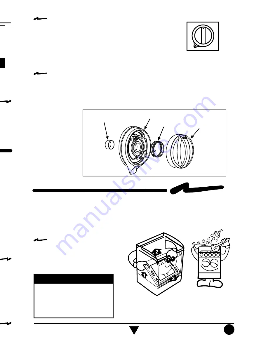
• Para ensamblar las perillas Super Safe:

1.- Coloque el resorte sobre la base de la perilla.

2.- Coloque la perilla encima del resorte. La marca

     roja de la perilla debe apuntar hacia arriba mientras

     que la palanca de la base apunta hacia abajo.

3.- Inserte el collar metálico en la perilla.

• 

To assembly the knobs:

1.- Put the spring on the knob base.

2.- Put the knob on the spring. The red mark must be upside

     while the lever of the base must be pointed down.

3.- Insert the metallic ring on the knob shaft.

1.- Coloque la válvula en posición de Apagado.

2.- La 

perilla 

debe estar 

en posición 

ver

tical, con 

la marca

     roja hacia arriba y la palanquita apuntando hacia la

     izquierda (Ver la figur

a de la derecha).

3.- Inserte la per

illa en la válvula asegurándose que el

     pernito de atrás de la per

illa entre en el agujero del

     frente de perillas

, empuje firmemente la per

illa hasta

     que tope con el frente de perillas

.

• En caso de retirar las perillas para limpieza, coloquelas de acuerdo a las

  siguientes instrucciones:

• 

How to install the knobs if you remove them for cleaning:

1.- The valve should be in off position.

2.- The knob should be in vertical position, the red mark

     up and the small lever to the left side (See the illustration)

3.- Insert the knob in the valve, be sure that the small pin behind

     the knob is aligned to the hole on the manifold panel, push

     the knob until the face of the manifold panel.

Collar Metálico

Base de la Perilla

Resorte

Perilla

Metallic Ring

Knob Base

Spring

Knob

13

Summary of Contents for ACK2400

Page 1: ...IS MANUAL CONTAINS IMPORTANT INFORMATION READ IT BEFORE FIRST USE OF YOUR RANGE INSTALLATION USE AND CARE MANUAL Printed in Mexico 12 2000 Stylemaster 98008737 R 0 Covers the following Models ACK2400 ACK2601 ACK2635 ACK3411 ACK3654 ACK3786 ...

Page 2: ...P P Vá Q 2 C Enc Ele Ind Sup Solo e ACK26 Int Sol Solo e ACK26 Ca Solo y AC Ca AC Fren Solo e ACK34 Xpre Pe Solo ACK Í ...

Page 3: ...s or wear loose clothing your clothes may ignite if contact by open flames WARNING 61 cm min Proper installation is your responsibility A qualified technician or Service technician must install this range Remove all packing material and put the range accessories in their places Select the best location in your kitchen for your range protected from wind and with enough space to open the oven door D...

Page 4: ...4 ...

Page 5: ...move the Venturi tubes these are the tubes that provide the gas to the burners and the cooktop moving it from right to left while you lift the cooktop to release the clips Disconnect the spark plugs wires from the ignition module according to the model Remove the side channels and fix them to the counter top using the same screws provided with the range see the illustration Prepare the kitchen cab...

Page 6: ...6 Re m qu De Co y c Co qu Re De Re Co En En al t Co cri Ve pá Tub integ Regul integr Válvu Gas i estufa P ...

Page 7: ...rner then push or pull the air shutter until you get a blue flame NATURAL GAS OPERATING PRESSURE 7 inches Water Column GAS L P OPERATING PRESSURE 11 inches Water Column To make it easier to move the appliance the installer should loop the 3 8 copper tubing as shown in the illustration If the installation is not new you should clean it in order to avoid the obstruction of orifices and or pilots Con...

Page 8: ...8 ...

Page 9: ... BURNERS To turn on the surface burners with independent electronic ignition Some models see page 2 have independent electronic ignition to operate it push the button located on the left side of the manifold panel while you push and turn the desired knob Release the ignition button when the burner lights Knob in ignition position OFF MINIMUM FLAME MAXIMUM FLAME ELECTRONIC IGNITION BUTTON SURFACE B...

Page 10: ...10 r ...

Page 11: ...n to change the rack position follow the steps To remove the oven rack 1 Pull the oven rack until it stops 2 Lift the front part 3 Pull it again until it is released To install the oven rack 1 Push the oven rack until it stops 2 Lift the front part 3 Push it again until it stops An extra rack position is provided for special cooking operations other than baking such as roasting where a large roast...

Page 12: ...12 A lu p A la ti y d 1 2 3 A S a in L p p A n L la s p ...

Page 13: ...void covering the side grooves Do not use caustic soda or cleaning agents which contain it to clean the range Failure on following the above will permanently damage the surfaces where it is applied IMPORTANT To assembly the knobs 1 Put the spring on the knob base 2 Put the knob on the spring The red mark must be upside while the lever of the base must be pointed down 3 Insert the metallic ring on ...

Page 14: ...14 Ase est Abr Cie pas No Apa Lla aut No oca exp Interrup Termos Relev ...

Page 15: ...________ DEALER SIGNATURE AND STAMP AUTHORIZED REPRESENTATIVE Indicate precise street section state and zip code IMPORTANT NOTE WARRANTY INDUSTRIAS ACROS WHIRLPOOL S A DE C V Carretera Panamericana km 280 C P 38020 Celaya Gto phone 4 614 50 44 in the terms of this policy we warranty to the buyer and the consumer of this range identified in this following policy COVERED CONCEPTS Manufacturing defec...

Page 16: ...16 So ...

Page 17: ...O No parte 98008736 Rev 0 LEA CUIDADOSAMENTE ESTE INSTRUCTIVO ANTES DE USAR POR PRIMERA VEZ SU ESTUFA Impreso en México 12 2000 Stylemaster 98008737 R 0 P Pri Sty Ampara los siguientes Modelos ACK2400 ACK2601 ACK2635 ACK3411 ACK3654 ACK3786 ...

Page 18: ...2400 y ACK3411 Interruptor Luz en Puerta de Horno Solo en modelos ACK2635 y ACK3786 Solo en modelos ACK2601 ACK2635 y ACK3654 Quemadores Multiposición Capelo de Cristal Solo en modelos ACK3654 y ACK3786 Termostato de Horno Válvula de Seguridad en Capelo Solo en modelo ACK3786 Características eléctricas nominales para los modelos ACK2400 ACK3411 ACK2654 y ACK3786 Solo en modelos ACK2635 y ACK3786 1...

Page 19: ...a del horno No instale gabinetes o muebles de cocina encima de la estufa Si instala campana extractora colóquela a 61 cm como mínimo de la cubierta de la estufa Si su estufa cuenta con accesorios eléctricos colóquela cerca de un tomacorriente de pared No use extensiones eléctricas o contactos múltiples 61 cm mínimo Peligro de Incendio y o Quemaduras No permita que los niños usen o jueguen con la e...

Page 20: ...re las parrillas quemadores superiores y sus tapas Deslice la estufa sobre la cubierta de la cocina sin llegar hasta el fondo Conecte la línea de gas como se indica en la página 6 y verifique con agua jabonosa que no existan fugas de gas Realice cuidadosamente las conexiones eléctricas necesarias y deslice la estufa hasta el fondo Coloque nuevamente los quemadores superiores las tapas de los quema...

Page 21: ...ire completamente la cubierta superior de la estufa y los tubos Venturi que conducen el gas a los quemadores Retire los canales laterales de la estufa y fíjelos en la cubierta de la cocina con los mismos tornillos que traía la estufa ver figura Montaje Tipo Drop In A C B D 30 518 29 7 723 812 20 518 29 7 464 552 Dim A Dim B Dim C Dim D Tamaño de Estufa CORTES NECESARIOS EN LA CUBIERTA DE LA COCINA...

Page 22: ...Coloque los quemadores superiores tapas de quemadores y en su caso el capelo de cristal Verifique que la válvula de seguridad funcione correctamente como se menciona en la página 11 l it ack at that side CONEXIÓN DE LA ESTUFA A LA LÍNEA DE GAS NOTA El material mostrado para instalacion no viene con la estufa NOTA Su estufa puede estar equipada de fábrica con 1 Tubo de Alimentacion ó 2 Regulador de...

Page 23: ... entrada de aire primario a los quemadores para obtener una adecuada mezcla de aire gas y así tener un buen funcionamiento de la estufa PRESIÓN DE OPERACIÓN PARA GAS NATURAL 1 74 kPa 18 cm Col agua GAS L P PRESIÓN DE OPERACIÓN 2 74 kPa 28 cm Col agua Con el fin de facilitar el movimiento del aparato el instalador debe hacer una espiral con el tubo flexible de cobre e instalar una llave de paso en ...

Page 24: ...ición de Piloto TORNILLO DE AJUSTE DE PILOTO HORNO EW ENCENDIDO MANUAL DE QUEMADORES SUPERIORES Para encender los quemadores superiores Acerque un cerillo encendido al quemador y al mismo tiempo presione y gire 1 4 de vuelta la perilla del quemador correspondiente Perilla en posición de encendido APAGADO FLAMA MÍNIMA FLAMA MÁXIMA IMUM ME Ajuste del aire del quemador del horno Retire la parrilla de...

Page 25: ...eben estar fríos 2 Tome el quemador multiposición levántelo y girélo 180 grados media vuelta 3 Vuelva a colocarlo asegurándose que la bujía de encendido haya entrado en la perforación del quemador QUEMADORES MULTIPOSICIÓN Algunos modelos tienen los quemadores multiposición al centro de la estufa o en los extremos QUEMADORES SIN ROTAR QUEMADORES ROTADOS BOTÓN DE ENC ELECTRÓNICO S t t S b 1 2 3 S e ...

Page 26: ...ico o metal para limpiarlo use agua jabonosa y una esponja t Para encender el horno con termocontrol de encendido manual 1 Encienda un cerillo y colóquelo cerca del agujero de la charola del horno al mismo tiempo presione y gire 1 4 de vuelta la perilla del horno 2 Verifique que el quemador del horno se haya encendido Para encender el horno con termocontrol de encendido con piloto 1 Encienda un ce...

Page 27: ... estufa 1 Empuje la parrilla hasta el tope 2 Levante la parrilla de la parte frontal 3 Empújela nuevamente para que llegue hasta el fondo del horno PARRILLA DEL HORNO Para hornear alimentos muy grandes puede usarse el soporte extra de la parte inferior El horno tiene 4 diferentes soportes para la parrilla la parrilla tiene un tope que evita que se salga completamente del horno para cambiar la posi...

Page 28: ...perillas Super Safe que son perillas que brindan seguridad adicional para su familia a través de un candado individual Las perillas Super Safe funcionan a través de una palanca que activa un candado que impide girar la perilla para encender el quemador Active el candado individual de las perillas cuando no utilice su estufa PERILLAS SUPER SAFE PERILLA SUPER SAFE Perilla con Candado NO GIRA Perilla...

Page 29: ...e IMPORTANTE Puede usar papel aluminio para forrar la charola del horno teniendo cuidado de NO tapar las ranuras de la misma C Reg soa clea You not eac 1 2 3 Do age ran Fail per wh Para ensamblar las perillas Super Safe 1 Coloque el resorte sobre la base de la perilla 2 Coloque la perilla encima del resorte La marca roja de la perilla debe apuntar hacia arriba mientras que la palanca de la base ap...

Page 30: ...W según modelo Módulo de Encendido 4 6 u 8 salidas según modelo Interruptor Luz Horno en Termostato según modelo Interruptor de Encendido Electrónico Independiente según modelo L N Interruptor Termostato Bidireccional para Encendido Electrónico según modelo Diagrama Eléctrico Estufa con Encendido Electrónico y Termostato Bidireccional Interruptor Luz de Horno en Frente Perillas según modelo Interr...

Page 31: ...ucto no ha sido operado de acuerdo con el instructivo de instalación y uso de la estufa Cuando el producto ha sido alterado o reparado por personas o establecimientos no autorizados por Servicio Acros Whirlpool PROCEDIMIENTO PARA HACER EFECTIVA LA GARANTÍA Al considerar el comprador que ha ocurrido alguno de los eventos amparados por esta póliza deberá ponerse en contacto con alguno de los estable...

Page 32: ...s MINATITLÁN VER Tels 223 71 93 y 223 70 31 Av Lerdo No 41 Col Centro MONTERREY N L Tels 83 29 21 00 y 83 86 21 31 Centro Industrial Acros Whirlpool Carr MiguelAlemánkm16 695 6 Apodaca N L MORELIA MICH Tel 324 42 21 Obrageros de Nurio No 194 C Col Vasco de Quiroga PUEBLA PUE Tels 01 800 830 04 00 Calle 31 Pte No 2727 Col Benito Juárez QUERÉTARO QRO Tel 12 37 66 Wenceslao de la Barquera No 22 C Col...

Reviews: