background image

4

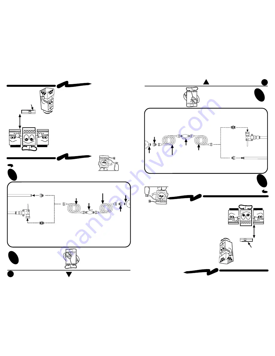
Conexión

4

Gas Supply 

Connection

GAS SUPPLY CONNECTION

CONEXIÓN DE LA ESTUFA A LA LÍNEA DE GAS

Para conectar su estufa, utilice el material especificado en la figura

de abajo.

1

2

Cheque con agua jabonosa

que no existan fugas.

2

Check with soap solution for leaks.

To connect the range, use the material shown in the bottom figure.

1

Installation

EXHAUST DEVICE

61 cm

min.

• Proper installation is your responsibility

. A

 qualified

  technician or Service technician m

ust install this

  range

.

• Remove all packing material and put the range

  accessories in their places.

• Select the best location in your kitchen for your

  range, protected from wind and with enough space

  to open the oven door.

• Do not install cabinetry directly above the range.

• If you will install an exhaust device, put it at 61 cm

  minimum from the range cooktop.

• If your range has a power cord, it must be installed

  near an electrical wall outlet.

• Do not use extension cords or m

ultiple outlets.

Instalación

CAMPANA EXTRACTORA

•  La  instalación  apropiada  es  su  responsabilidad.

  Un técnico calificado o un técnico de Servicio debe

   instalar esta estufa.

• Retire los elementos de empaque y coloque  los accesorios

  de la estufa.

• Seleccione la mejor ubicación para su estufa, no debe

  quedar expuesta a corrientes de aire y debe tener espacio

  suficiente para abrir la puerta del horno.

• No instale gabinetes o muebles de cocina encima de la

  estufa.

• Si instala campana extractora, colóquela a 61 cm  como

  mínimo, de la cubierta de la estufa.

• Si su estufa cuenta con accesorios eléctricos, colóquela

  cerca de un tomacorriente de pared.

• No use extensiones eléctricas o contactos múltiples.

61 cm

mínimo

NOTA: El material mostrado para instalacion no viene con la estufa.

NOTA: Su estufa puede estar equipada de fábrica con:

            1.- Tubo de Alimentacion ó

            2.- Válvula de Corte de Gas.

Tubo de Alimentación

integrado a la estufa

Llave de paso

de 9,5 mm (3/8")

Cople-Niple de 9,5 mm (3/8"NPT)

a 9,5 mm(3/8")cónica

Tubo de cobre con tuercas

cónicas de 9,5 mm (3/8")

Tubo de cobre con tuercas

cónicas de 9,5 mm (3/8") de

longitud necesaria para llegar

al gas

 Cople-Niple de

9,5 mm (3/8"NPT)

Regulador

de gas

Válvula de Corte de

Gas 

integrado a la

estufa

Niple de 9,5 mm(3/8"NPT)

a (3/8")cónica

NOTE: The m

aterial shown for installation is not provided with the

            range.

NOTE: The range could be equipped from the factory with

            one of the following accesories:

            1.- Gas Inlet Tu

be Fitting or

            2.- Shut Off Gas V

alve.

3/8" shut off

valve

Gas Inlet T

ube Fitting

integrated to the range

3/8" NPT to 3/8" brass pipe

fitting Hex. adapter

3/8" copper 

pipe

with 5/8" flared

type nut

 Gas

regulator

3/8" copper pipe with

5/8" flared type nut.

Necessary

length to reach the

gas

 3/8" brass pipe

fitting

Hex. adapter

Shut Off G

as

Valve

integrated to the

range

3/8" NPT to 3/8" brass

pipe fitting Hex. adapter

Summary of Contents for ACE2737

Page 1: ...ACE2737 ACE2868 ACE3527 ACE3657 ACE3757 ACE3788 ACE3889 Impreso en México 2002 SM98013644 Rev 0 Part No 98013643 THIS MANUAL CONTAINS IMPORTANT INFORMATION READ IT BEFORE FIRST USE OF YOUR RANGE ACE2737 ACE2868 ACE3527 ACE3657 ACE3757 ACE3788 ACE3889 INSTALLATION USE AND CARE MANUAL Covers the following models Printed in Mexico 2002 SM98013644 Rev 0 ESTUFAS RANGES ...

Page 2: ...orno Termostato Bidireccional Termostato de Horno con Piloto Duoflama Quemadores Multiposición Capelo de Cristal Respaldo Superior Cubierta Superior Porcelanizada Porcelanizada 2 2 2 2 Porcelanizada Porcelanizada Porcelanizada Porcelanizada 3 3 3 3 Encendido Electrónico de Horno Interruptor Luz de Horno en Perilla Ventana de Horno Panorámica Panorámica Panorámica Panorámica Panorámica Panorámica 2...

Page 3: ...eath fire or explosion WARNING 127 V 10 50 60 Hz 1 0 A Max Características eléctricas nominales Electric Characteristics 127 V 10 50 60 Hz 1 0 A Max Oven Thermostat with Pilot Top Burners Porcelainized Griddle Backguard Top Grates Burner Valves Oven Rack Oven Window Cooktop Broiler Independent Electronic Ignition for Surface Burners Oven Light Switch Xpress Super Burner Waist High Broiler Integrat...

Page 4: ...ficiente para abrir la puerta del horno No instale gabinetes o muebles de cocina encima de la estufa Si instala campana extractora colóquela a 61 cm como mínimo de la cubierta de la estufa Si su estufa cuenta con accesorios eléctricos colóquela cerca de un tomacorriente de pared No use extensiones eléctricas o contactos múltiples 61 cm mínimo NOTA El material mostrado para instalacion no viene con...

Page 5: ...ir shutters Remove the knobs 1 2 3 HOW TO ADJUST THE FLAMES How to adjust the air for surface burners I M P O R T A N T NOTE Because of different altitudes above sea level and variations in the supply of gas you may need to adjust the main air intake to the burners This will result in a better air gas mixture and thus a better operation NATURAL GAS OPERATING PRESSURE 7 inches Water Column GAS L P ...

Page 6: ... son azules repita desde el paso B al finalizar apriete nuevamente el tornillo F Coloque la charola del horno y la parrilla nuevamente en su lugar The models with thermostat have a pilot in the oven burner to adjust it 1 Without the manifold panel locate the adjustment screw on the thermostat see the illustration on the right side 2 Remove the oven tray see page 13 and turn the knob approximately ...

Page 7: ...ición de flama máxima Perilla en posición de encendido Para encender los quemadores superiores con encendido electrónico integrado en la perilla Some models see page 2 include a programmable burner The programmable burner operates with the timer with a range from 1 59 hours to 1 minute The burner is located in the right front side of the range How to operate the programmable burner 1 Push the butt...

Page 8: ...el suministro de energía eléctrica llegara a fallar cuando el quemador está programado éste se apagará 8 MULTIPOSITION BURNERS Some models see page 2 have multiposition burners the position of these burners can be changed allowing to concentrate the heat for large pots Some models have the multiposition burners on the left side of the range To rotate the burners 1 Ensure that the burners are cold ...

Page 9: ...and is ignited electronically How to light the oven burner with bidirectional thermostat 1 Turn the oven knob counter clockwise until it matches with some oven temperature push the knob 3 or 4 seconds and the oven burner will ignite automatically Remain pressed the knob until the burner is on when you release the knob 10 seconds approximately 2 Select the desired temperature How to light the broil...

Page 10: ...nity the electrical supply is at 50 Hz move the small lever located on the back of the clock to the left position COMAL DE ALUMINIO ANTIADHERENTE Algunos modelos ver Pág 2 cuentan con comal de aluminio con acabado antiadherente para usarlo debe retirar una parrilla y colocarlo en lugar de ésta NOTA Use el comal de aluminio con FLAMA BAJA NOTA El comal con acabado antiadherente color negro en la su...

Page 11: ...ack 1 Pull the oven rack until it stops 2 Lift the front part 3 Pull it again until it is released To install the oven rack 1 Push the oven rack until it stops 2 Lift the front part 3 Push it again until it stops An extra rack position is provided for special cooking operations other than baking such as roasting where a large roasting container will require more heat and therefore need to be close...

Page 12: ...s these are knobs with a lever that activate an extra safety mechanism for children If you do not have children at home is not necessary to activate the lever each time you turn off the burners The knob can be turned if the lever indicates the unlock position If the lever indicates the lock position the knob can not be turned Once you have turned on the burner the lever must be maintained on unloc...

Page 13: ...uminum foil to wrap the oven tray avoid covering the side grooves To assembly the knobs 1 Put the spring on the knob base 2 Put the knob on the spring The red mark must be upside while the lever of the base must be pointed down 3 Insert the metallic ring on the knob shaft How to install the knobs if you remove them for cleaning 1 The valve should be in off position 2 The knob should be in vertical...

Page 14: ...or Luz de Horno en Puerta según modelo Foco de Horno 40 W según modelo Módulo de Encendido 4 6 u 8 salidas según modelo Interruptor Luz Horno en Termostato según modelo Interruptor de Encendido Electrónico Independiente según modelo Reloj Válvula Termopar L N Interruptor del Quemador con Timer para Encendido Electrónico según modelo Interruptor Termostato Bidireccional para Encendido Electrónico s...

Page 15: ...no de los eventos amparados por esta póliza deberá ponerse en contacto con alguno de los establecimientos indicados en la lista de Centros de Servicio Autorizados aquí incluida Esta garantía quedará sin efecto cuando personas o establecimientos no autorizados intervengan en la reparación o reemplazo de componentes de fabricación TÉRMINO Esta garantía tiene una vigencia de UN AÑO a partir de la fec...

Page 16: ...33 Col Centro VILLAHERMOSA TAB Tel 01 800 83 00400 Cristóbal Colón No 231 Col Lidia Esther TUXTLA GTZ CHIS Tel 961 612 8554 Novena Ote Sur No 555 Col Centro Centros de Atención al Consumidor SERVICIO ACROS WHIRLPOOL En otras ciudades de la República Mexicana contamos con una amplia red de talleres autorizados Llame sin costo al 01 800 8 300 400 Fuera de la República Mexicana encontrará nuestros se...

Reviews: