SERIES AP470 ACROPACK
USER
’S MANUAL
Acromag, Inc. Tel: 248-295-0310
- 32 -
http://www.acromag.com
- 32 -
www.acromag.com
The default value is 00, setting 3-4us debounce period. This register is
cleared following a reset (setting debounce to 3-4us). Note that the
debounce clock must be reselected to re-enable debounce following a reset
(see below).
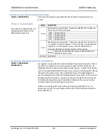
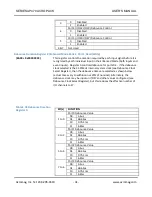
When using I/O47 as the debounce clock the effective debounce duration
can be calculated by taking the clock period (in seconds) and multiplying it by
the appropriate constant shown in Table 3.19 below. The debounce will have
an error of ±2 clock periods.
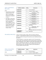
Table 3.19 Debounce Duration
Clock Multiplier Selection
Debounce Duration
Selection
Debounce Count
Constant
00
125
01
2000
10
31250
11
250000
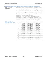
Debounce Duration Register 1 (Enhanced Mode Bank 2, Port 2, Read/Write)
(BAR0 + 0x0000 0010)
This register controls the duration required by each input signal before it is
recognized by each individual input in the Enhanced Mode (both inputs and
event inputs). Register 1 controls debounce for ports 4 & 5. If the debounce
clock selected is the 31.25MHz internal system clock (see Debounce Clock
Select Register), then the debounce times are selected as shown below
(actual times vary to within minus 25% of nominal). Alternately, the
debounce clock may be input on I/O47 and other values configured (see
Debounce Clock Select Register), but this reduces the effective number of
I/O channels to 47.
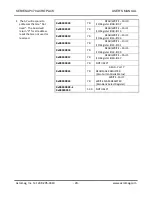
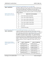
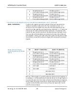
Table 3.18 Debounce Duration
Register 0:
Bit(s)
FUNCTION
1 to 0
Port 4 Debounce Value
00
3-4us
01
48-64us
10
0.75-1ms
11
6-8ms
3 to 2
Port 5 Debounce Value
00
3-4us
01
48-64us
10
0.75-1ms
11
6-8ms
7 to 4
NOT USED
The default value is 00, setting 3-4us debounce period. This register is
cleared following a reset (setting debounce to 3-4us). Note that the
debounce clock must be reselected to re-enable debounce following a reset
(see below).

