SERIES AP470 ACROPACK
USER
’S MANUAL
Acromag, Inc. Tel: 248-295-0310
- 39 -
http://www.acromag.com
- 39 -
www.acromag.com
Programming Example
The following example outlines the steps necessary to configure the AP470
for Enhanced Mode operation, to setup event-generated interrupts,
configure debounce, and read and write I/O. It is assumed that the module
has been reset and no prior (non-default) configuration exists.
For this example, we will configure port 0 I/O points as a four channel
change-of-state detector. For change-of-state detection, both positive and
negative polarities must be sensed and thus, two channels are required to
detect a change-of-state on a single input signal. I/O00-I/O03 will be used to
detect positive events (low-to-high transitions); I/O04-07 will be used to
detect negative events (high-to-low transitions). I/O00 and I/O04 will be tied
to the first input signal, I/O01 & I/O05 to the second, I/O02 & I/O06 to the
third, and I/O03 & I/O07 to the fourth. Any change-of-state detected on
these input signals will cause an interrupt to be generated.
1.
After power-up or reset, the module is placed in the Standard
Operating Mode. To switch to Enhanced Mode, execute four
consecutive write cycles to port 7 with the following data: 07H first,
followed by 0DH, followed by 06H, then 12H. At this point, you are in
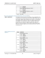
Enhanced Mode bank 0. Port 7 is used to access register banks 1 & 2.
2.
Write 80H to the port 7 address to select register bank 2 where
debounce will be configured for our port 0 input channels. At this
point, you are in Enhanced Mode Bank 2 where access to the
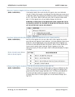
debounce configuration registers is obtained.
3.
For our example, we want use the 31.25MHz internal system clock to
generate our debounce time. By default, the debounce clock is taken
from I/O47 (pin 94 of P2). Select the 31.25MHz internal system clock
as the debounce clock by writing 01H to the port 3 address of this
bank (Debounce Clock Select Register).
4.
The default debounce duration is 4µs with the 31.25MHz clock
selected in step 3. Write 01H to the port 1 address of this bank to
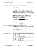
select a 64µs debounce time (Debounce Duration Register 0). An
incoming signal must be stable for the entire debounce time before
it will be recognized as a valid input transition. Note that Debounce
Duration Register 1 (port address 2) would be used to configure
debounce durations for I/O points of ports 4 & 5.
5.
Enable the debounce circuitry for port 0 inputs by setting bit 0 of the
Debounce Control Register. Write 01H to the Port 0 address of this
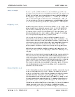
bank (Debounce Control Register). If the module had been
configured earlier, you would first read this register to check the
existing settings of debounce enable for the other ports of this
module with the intent of preserving their configuration by adjusting
the value written above.


