


Product and Installation Manual: Sentry Barrier TL-4 ThrieBeam System
ACP
| September 2020 |
Page
9
New South Wales
Sydney
02 8708 4400
Victoria
Melbourne
02 8708 4400
Queensland
Brisbane
07 3442 6200
Western Australia
Perth
02 9772 4172
System Design and Design Considerations
Curbs
As with all road side safety hardware, the
Sentry Barrier TL-4 ThrieBeam System
has been
designed and tested so that the centre of gravity of the impacting vehicle is at a constant height in
relation to the system. For this reason, it is preferred that curbs or channels are not in front or directly
behind the
Sentry Barrier TL-4 ThrieBeam System
as they may result in altering the height of the
vehicle at impact.
If interaction with a curb cannot be avoided consult the local Road Controlling Authority guidelines
regarding allowable curb heights, curb shapes, and barrier offset distance.
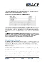
Slopes
The
Sentry Barrier TL-4 ThrieBeam System
can be installed on ground with a maximum cross fall
of 6H:1V. For steeper slopes it is recommended that the system is installed no closer than 400 mm
to the batter hinge point of the slope, please refer to below for guidance. If installations with less
clearance are required, please contact your local ACP Distributor.
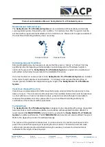
Batter Hinge Proximity
The offset proximity of the
Sentry Barrier TL-4 ThrieBeam System
to the batter hinge point of a
slope is dependent upon the design containment level of the road. For a TL-3 containment level, the
minimum proximity to the hinge point shall be minimum 400 mm from the back edge of the post to
the Batter Hinge Point as shown in the figure below. For a TL-4 containment level, the minimum
proximity to the hinge point measured from the face of the rail, shall be equal to the expected
deflection at TL-4, which is 1530 mm. Refer to below figure for guidance.
Installations in proximity to a batter hinge point should also be considered within the requirements of
the road controlling authority Extended Design Domain requirements, where applicable.


