background image

661 Brea Canyon Rd., Suite 3

Walnut, CA 91789

tel: 909.598.7388, fax: 909.598.0218

© Copyright 2009 Acnodes, Inc.

All rights reserved. Product description and product specifications

are subject to change without notice. For latest product information,

please visit Acnodes’ web site at www.acnodes.com.

RMC 7189

1U Rackmount System

Inner Rails

The motherboard chassis includes a set of inner rails in two sections: inner rails and inner rail extensions.
The inner rails are pre-attached and do not interfere with normal use of the chassis if you decide not to
use a server rack. Attach the inner rail extension to stabilize the chassis within the rack.

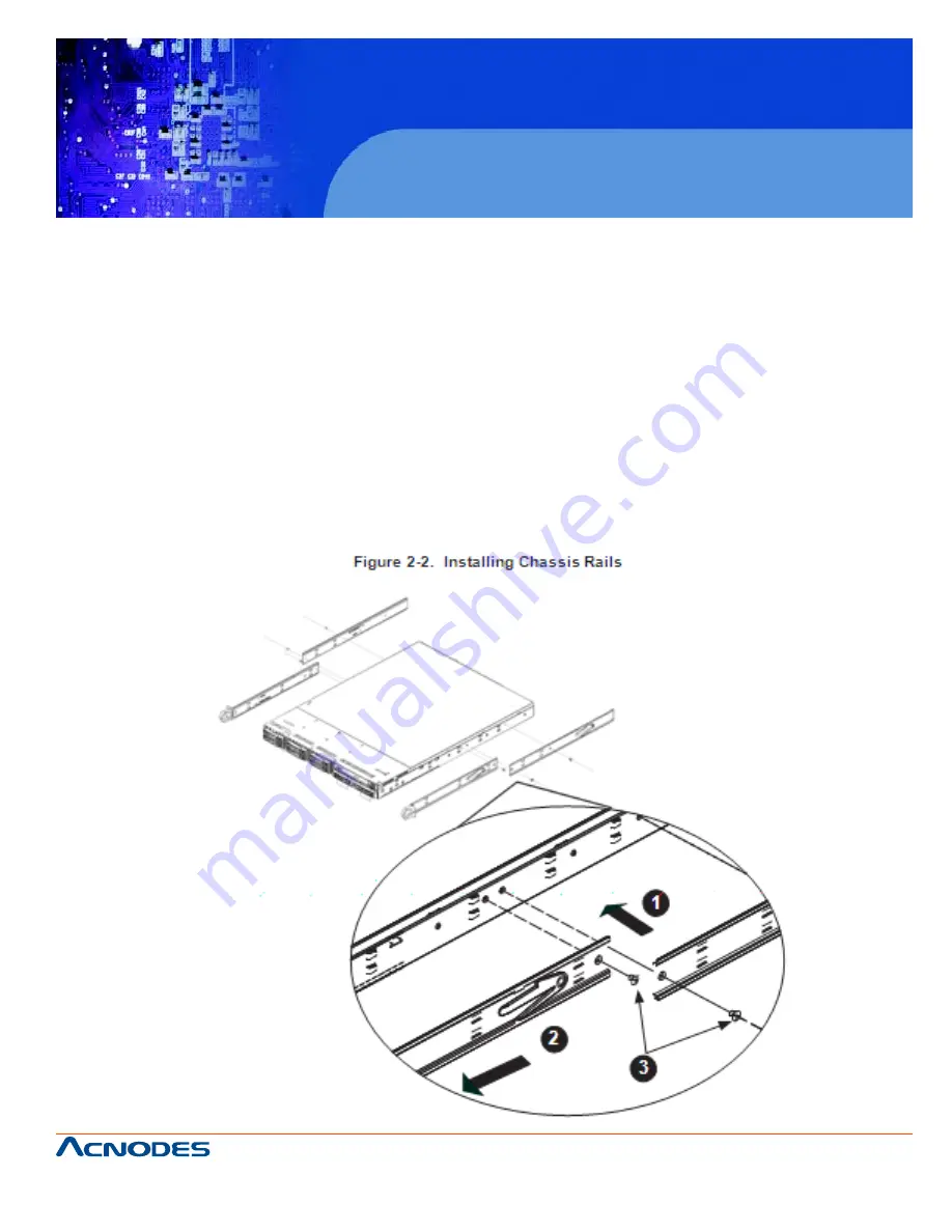
Installing the Rack Rails

1.   Place the inner rack extensions on the side of the chassis aligning the hooks of the chassis with the
rail extension holes. Make sure the extension faces "outward" just like the pre-attached inner rail.

2.   Slide the extension toward the front of the chassis.

3.   Secure the chassis with two screws as illustrated.

4.   Repeat steps 1-3 for the other inner rail extension.

Summary of Contents for RMC 7189

Page 1: ...t description and product specifications are subject to change without notice For latest product information please visit Acnodes web site at www acnodes com RMC 7189 1U Rackmount System User Manual RMC7189 1U Rackmount Computer comes with Intel Xeon X5600 E5600 L5600 series processor Intel Xeon X5500 E5500 L5500 series processor ...

Page 2: ...y in the State of California USA The State of California County of Santa Clara shall be the exclusive venue for the resolu tion of any such disputes Acnodes s total liability for all claims will not exceed the price paid for the hardware product FCC Statement This equipment has been tested and found to comply with the limits for a Class A digital device pursuant to Part 15 of the FCC Rules These l...

Page 3: ...cluded with the server system and describes the main features of the embedded board and the RMC7189 chassis Chapter 2 Server Installation This chapter describes the steps necessary to install the Acnodes RMC7189 into a rack and check out the server configuration prior to powering up the system If your server was ordered without the processor and memory components this chapter will refer you to the...

Page 4: ...ectors headers and jumpers Refer to this chapter when adding or removing processors or main memory and when reconfiguring the motherboard Chapter 6 Advanced Chassis Setup Refer to Chapter 6 for detailed information on the RMC7189 1U rackmount server chassis You should follow the procedures given in this chapter when in stalling removing or reconfiguring drives and when replacing system power suppl...

Page 5: ...tents CHAPTER 1 INTRODUCTION 1 1 Overview 1 1 2 Serverboard Features 2 Processor 2 Memory 2 UIO 2 SATA 2 PCI Expansion Slots 2 Onboard Controllers Ports 2 Graphics Controller 2 Other Features 2 1 3 Server Chassis Features 4 System Power 4 PCI Expansion Slots 4 Control Panel 4 I O Backplane 4 Cooling System 4 CHAPTER 2 INSTALLATION 2 1 Overview 5 2 2 Unpacking the System 5 2 3 Preparing for Setup 5...

Page 6: ...oading 7 Reliable Ground 7 2 4 Installing the System in to a Rack 8 Identifying the Sections of the Rack Rails 12 Inner Rails 12 Outer Rails 12 Installing the Server into a Telco Rack 12 2 5 Checking the Serverboard Setup 12 2 6 Checking the Drive Bay Setup 14 CHAPTER 3 System Interface 3 1 Overview 16 3 2 Control Panel Buttons 16 Reset 16 Power 16 UID 16 3 3 Control Panel LEDs 17 Universal Inform...

Page 7: ...MOTHERBOARD SETUP 5 1 Handling the Serverboard 23 Precautions 23 Unpacking 23 5 2 Processor and Heatsink Installation 23 Installing LGA1366 Processors 23 Installing the Heatsink 24 Removing the Heatsink 24 5 3 Connecting Cables 24 Connecting Data Cables 24 Connecting Power Cables 25 Connecting the Control Panel 25 5 4 I O Ports 26 5 5 Installing Memory 27 5 6 Adding PCI Cards 30 5 7 Serverboard De...

Page 8: ...ecautions 50 6 2 Control Panel 51 6 3 System Cooling 52 System Fan Failure 52 6 4 Drive Bay Installation Removal 53 Accessing the Drive Bays 53 Hard Drive Installation 55 DVD Drive Installation 55 6 5 Power Supply 56 RMC7185 56 CHAPTER 7 BIOS 7 1 Introduction 56 Starting BIOS Setup Utility 56 How To Change the Configuration Data 56 Start the Setup Utility 57 7 2 Main Setup 57 7 3 Advanced Setup Co...

Page 9: ...ease refer to our web site for informa tion on operating systems that have been certified for use with the RMC7189 In addition to the mainboard and chassis various hardware components may have been included with the RMC7189 as listed below o One slim DVD ROM drive o One mini USB to SATA adapter o Four sets of 4 cm counter rotating fans o One air shroud o One DVD ROM drive cable o One internal USB ...

Page 10: ...r installing memory UIO The RMC7189 is a specially designed serverboard that features Acnodes s UIO Universal I O tech nology UIO serverboards have a PCI Express x8 slot that can support any one of several types of UIO card types to add SAS ports additional LAN ports etc to the serverboard This allows the user to tailor the serverboard to their own needs Note the server does not come with a UIO ca...

Page 11: ...wer supply consisting of two power modules The system does not need to be shut down when replacing or removing a single power supply module The RMC7189 features a single 560W power supply module The system must be shut down when replacing or removing this power supply module PCI Expansion Slots A riser card on the right side of the chassis can sup port AOC PG i2 add on card to provide two Gb LAN p...

Page 12: ... please visit Acnodes web site at www acnodes com RMC 7189 1U Rackmount System Cooling System The RMC7189 chassis revolutionary cooling design has been optimized to provide sufficient cooling for dual CPU configurations The chassis includes an air shroud and four 4 cm counter rotating fans located in the middle of the chassis There is a Fan Speed Control Mode in BIOS that allows chas sis fan speed...

Page 13: ...de on a suitable location for the rack unit that will hold the Acnodes RMC7189 It should be situ ated in a clean dust free area that is well ventilated Avoid areas where heat electrical noise and electromagnetic fields are generated You will also need it placed near a grounded power outlet Read the Rack and Server Precautions in the next section 2 3 Preparing for Setup The box the RMC7189 was ship...

Page 14: ...he rack is stable before extending a component from the rack o You should extend only one component at a time extending two or more si multaneously may cause the rack to become unstable Server Precautions o Review the electrical and general safety precautions in Chapter 4 o Determine the placement of each component in the rack before you install the rails o Install the heaviest server components o...

Page 15: ...empera ture Tmra Reduced Airflow Equipment should be mounted into a rack so that the amount of airflow required for safe operation is not compromised Mechanical Loading Equipment should be mounted into a rack so that a hazardous condition does not arise due to uneven mechanical loading Circuit Overloading Consideration should be given to the connection of the equipment to the power supply circuitr...

Page 16: ...lready been mounted into a rack you can skip ahead to Sections 2 5 and 2 6 Note This rail will fit a rack between 26 and 33 5 deep There are a variety of rack units on the market which may mean the assembly procedure will differ slightly The following is a guideline for installing the RMC7189 into a rack with the rack rails provided You should also refer to the installation instructions that came ...

Page 17: ...s and inner rail extensions The inner rails are pre attached and do not interfere with normal use of the chassis if you decide not to use a server rack Attach the inner rail extension to stabilize the chassis within the rack Installing the Rack Rails 1 Place the inner rack extensions on the side of the chassis aligning the hooks of the chassis with the rail extension holes Make sure the extension ...

Page 18: ...m Outer Rails Installing the Outer Rails to the Rack 1 Attach the short bracket to the outside of the long bracket You must align the pins with the slides Also both bracket ends must face the same direction 2 Adjust both the short and long brackets to the proper distance so that the rail fits snugly into the rack 3 Secure the long bracket to the front side of the outer rail with two M5 screws and ...

Page 19: ...88 fax 909 598 0218 Copyright 2009 Acnodes Inc All rights reserved Product description and product specifications are subject to change without notice For latest product information please visit Acnodes web site at www acnodes com RMC 7189 1U Rackmount System ...

Page 20: ...Chassis into a Rack 1 Confirm that chassis includes the inner rails and rail extensions Also confirm that the outer rails are installed on the rack 2 Line chassis rails with the front of the rack rails 3 Slide the chassis rails into the rack rails keeping the pressure even on both sides you may have to depress the locking tabs when inserting When the server has been pushed completely into the rack...

Page 21: ...the Acnodes RMC7189 into a Telco type rack use two L shaped brackets on either side of the chassis four total First determine how far follow the server will extend out the front of the rack Larger chassis should be positioned to balance the weight between front and back If a bezel is included on your server remove it Then attach the two front brackets to each side of the chassis then the two rear ...

Page 22: ...ed to open the unit to make sure the serverboard is prop erly installed and all the connections have been made Removing the Chassis Cover Figure 2 5 1 Grasp the two handles on either side and pull the unit straight out until it locks you will hear a click 2 Remove the screws securing the top cover to the chssis 3 Slide the cover toward the rear of the chassis 4 Lift the cover off the chassis Check...

Page 23: ...serverboard area of the chassis 2 6 Checking the Drive Bay Setup Next you should check to make sure the peripheral drives and the Serial ATAdrives and Serial ATA backplane have been properly installed and all essential connec tions have been made Checking the Drives 1 For servicing the hard drives you will need to remove the top chassis cover 2 If you need to remove or install hard drives please r...

Page 24: ... you may need to take 3 2 Control Panel Buttons There are two push buttons located on the front of the chassis a reset button and a power on off button Reset Button The reset button reboots the system Power This is the main power button which is used to apply or turn off the main system power Turning off system power with this button removes the main power but keeps standby power supplied to the s...

Page 25: ...ny corrective ac tion you may need to take Universal Information LED When this LED blinks red quickly it indicates a fan failure and when blinking red slowly a power failure This LED will be blue when used for UID Unit Identifier When on continuously it indicates an overheat condition which may be caused by cables obstructing the airflow in the system or the ambient room temperature being too warm...

Page 26: ...rmation please visit Acnodes web site at www acnodes com RMC 7189 1U Rackmount System NIC2 Indicates network activity on LAN2 when flashing NIC1 Indicates network activity on LAN1 when flashing HDD Channel activity for all HDDs This light indicates IDE or SATAdrive activity when flashing Power Indicates power is being supplied to the system s power supply units This LED should normally be illumi n...

Page 27: ... green and a red LED o Green Each Serial ATA drive carrier has a green LED When illuminated this green LED on the front of the SATA drive carrier indicates drive activity A connection to the SATA backplane enables this LED to blink on and off when that particular drive is being accessed Please refer to Chapter 6 for instructions on replacing failed SATA drives o Red The red LED to indicate an SATA...

Page 28: ...m the system when removing or in stalling main system components such as the motherboard memory modules and floppy drive When disconnecting power you should first power down the system with the operating system first and then unplug the power cords of all the power supply units in the system o When working around exposed electrical circuits another person who is familiar with the power off control...

Page 29: ... Tempera ture Coefficient fuses on the mainboard must be replaced by trained service technicians only The new fuse must be the same or equivalent as the one replaced Contact technical support for details and support 4 2 General Safety Precautions Follow these rules to ensure general safety o Keep the area around the RMC7185 clean and free of clutter o The RMC7189 weighs approximately 37 lbs 16 8 k...

Page 30: ...ted circuit boards The following measures are generally sufficient to neutralize this difference before contact is made to protect your equipment from ESD o Use a grounded wrist strap designed to prevent static discharge o Keep all components and printed circuit boards PCBs in their antistatic bags until ready for use o Touch a grounded metal object before removing the board from the antistatic ba...

Page 31: ... subject to change without notice For latest product information please visit Acnodes web site at www acnodes com RMC 7189 1U Rackmount System 4 4 Operating Precautions Care must be taken to assure that the chassis cover is in place when the RMC7189 is operating to assure proper cooling Out of warranty damage to the system can occur if this practice is not strictly followed ...

Page 32: ...ed circuit boards it is important to handle them very carefully see Chapter 4 Also note that the size and weight of the serverboard can cause it to bend if handled improperly which may result in damage To prevent the serverboard from bending keep one hand under the center of the board to support it when handling The following measures are generally sufficient to protect your equipment from static ...

Page 33: ...or changing any hardware components Make sure that you install the processor into the CPU socket before you install the CPU heatsink o If you buy a CPU separately make sure that you use an Intel certified multi directional heatsink only o Make sure to install the serverboard into the chassis before you install the CPU heatsinks o When receiving a serverboard without a processor pre installed make ...

Page 34: ... on the side of the socket 3 Once the CPU and the socket are aligned carefully lower the CPU straight down into the socket Do not rub the CPU against the surface of the socket or its pins to avoid damaging the CPU or the socket 4 With the CPU in the socket in spect the four corners of the CPU to make sure that it sits level and is properly installed 5 Once the CPU is securely seated in the socket ...

Page 35: ...of the CPU so that the four mounting holes are aligned with those on the retention mechanism 2 Remove the thin layer of protective film from the copper core of the heatsink Warning The CPU may overheat if the protective film is not removed from the heatsink 3 Apply the proper amount of ther mal grease on the CPU If your heatsink came with a thermal pad please ignore this step 4 Screw in two diagon...

Page 36: ...e removed However if you do need to remove the heatsink please follow the instructions below prevent damage to the CPU or other compo nents 1 Unplug the power cord from the power supply 1 Unscrew and remove the heatsink screws in the sequence shown in the picture below 2 Hold the heatsink and gently wiggle it to loosen it from the CPU Do not use excessive force when doing this 3 Once the heatsink ...

Page 37: ...ng data cables with their locations noted should be connected See the motherboard layout for connector locations o DVD ROM drive cable SATA4 o SATA cables SATA0 SATA3 o Control Panel cable JF1 see next page Connecting Power Cables The embedded system has a 20 pin primary power supply connector designated JPW1 for connection to the ATX power supply Connect the appropriate connector from the power s...

Page 38: ...tion and product specifications are subject to change without notice For latest product information please visit Acnodes web site at www acnodes com RMC 7189 1U Rackmount System 5 4 I O Ports The I O ports are color coded in conformance with the PC 99 specification See Figure 5 2 below for the colors and locations of the various I O ports ...

Page 39: ...each DIMM vertically into its slot Pay attention to the notch along the bottom of the module to prevent inserting the DIMM module incorrectly see Figure 5 5 3 Gently press down on the DIMM module until it snaps into place in the slot Repeat for all modules Memory Support The embedded system supports up to 96 GB of registered ECC DDR3 1333 1066 800 SDRAM in 12 slots RDIMM modules are supported Note...

Page 40: ...88 fax 909 598 0218 Copyright 2005 Acnodes Inc All rights reserved Product description and product specifications are subject to change without notice For latest product information please visit Acnodes web site at www acnodes com RMC 7189 1U Rackmount System ...

Page 41: ...88 fax 909 598 0218 Copyright 2009 Acnodes Inc All rights reserved Product description and product specifications are subject to change without notice For latest product information please visit Acnodes web site at www acnodes com RMC 7189 1U Rackmount System ...

Page 42: ...t System 5 6 Adding PCI Cards PCI Expansion Slots Riser cards are used to support add on cards to the system See the tables below for the expansion cards that may be used in the serverboard chassis PCI Card Installation Before installing a PCI add on card make sure you install it into the correct riser card Begin by releasing the locking tab that corresponds to the slot you wish to populate Insert...

Page 43: ...189 1U Rackmount System 5 7 Serverboard Details Notes Jumpers not indicated are for test purposes only When LE1 LED is on the onboard power connection is on Make sure to unplug the power cables before removing or installing components IPMI Intelligent Platform Management Interface 2 0 is supported by the embedded system Warning To provide adequate power to the add on cards installed on the serverb...

Page 44: ...88 fax 909 598 0218 Copyright 2005 Acnodes Inc All rights reserved Product description and product specifications are subject to change without notice For latest product information please visit Acnodes web site at www acnodes com RMC 7189 1U Rackmount System ...

Page 45: ... and JPW3 must also be con nected to the power supply to provide power for the processor s See the table on the right for pin definitions Warning To prevent damage to your power supply or serverboard please use a power supply that contains a 20 pin and two 8 pin power connectors Be sure to connect these power connectors to the 20 pin and the two 8 pin power connectors on your serverboard for adequ...

Page 46: ... ler LED connection is located on pins 9 and 10 of JF1 Attach the NIC2 LED cable to display network activity Refer to the table on the right for pin definitions NIC1 LED The NIC1 Network Interface Control ler LED connection is located on pins 11 and 12 of JF1 Attach the NIC1LED cable to display network activity Refer to the table on the right for pin defini tions Overheat OH Fan Fail PWR Fail UID ...

Page 47: ...itch on the computer case Refer to the table on the right for pin definitions Power Button The Power Button connection is located on pins 1 and 2 of JF1 Mo mentarily contacting both pins will power on off the system This button can also be configured to function as a suspend button see the Power Button Mode setting in BIOS To turn off the power when set to suspend mode depress the button for at le...

Page 48: ...the chas sis is opened Serial Ports The Wake On LAN header is desig nated JWOL on the serverboard See the table on the right for pin defini tions You must also have a LAN card with a Wake On LAN connector and cable to use this feature Fan Headers On the JD1 header pins 1 4 are for an external speaker and pins 3 4 are for the internal speaker If you wish to use an external speaker connect it to pin...

Page 49: ...an external speaker If you wish to use the onboard speaker you should close pins 6 7 with a jumper ATX PS 2 Keyboard and PS 2 Mouse Ports The ATX PS 2 keyboard and the PS 2 mouse ports are located beside the USB ports See the table on the right for pin definitions Overheat LED Connect an LED to the JOH1 header to provide warning of a chassis overheat ing condition See the table on the right for pi...

Page 50: ...Bus header for the IPMI slot is located at IPMB Connect the appropriate cable here to use the IPMB I2C connection on your system UID Buttons There are two Unit Identification UID buttons on the serverboard The Front Panel UID Switch connects to pin 13 of JF1 The Rear UID Switch SW1 is located next to LAN2 Pushing the UID switch on the Front Control Panel will illuminate both the Rear UID and the C...

Page 51: ...yout pages for jumper locations Note On a two pin jumper Closed means the jumper is on both pins and Open means the jumper is either on only one pin or completely removed CMOS Clear JBT1 is used to clear CMOS which will also clear any passwords Instead of pins this jumper consists of contact pads to prevent accidentally clearing the contents of CMOS To clear CMOS 1 First power down the system and ...

Page 52: ...can reboot the system when a software application hangs Jumping pins 1 2 will cause WD to reset the system if an applica tion hangs Jumping pins 2 3 will generate a non maskable interrupt signal for the application that hangs See the table on the right for jumper set tings Watch Dog must also be en abled in BIOS Note When enabled the user needs to write their own application software in order to d...

Page 53: ...e ment Controller chip and the PHY chip The default is set to Open for normal operation See the table on the right for jumper settings ME Mode Select Closing jumper JP3 allows the user to bypass the SPI flash security and allow the manufacturer to flash the BIOS on the production line See the table on the right for jumper settings ME Recovery Jumper JP5 allows the user to select the ME Firm ware R...

Page 54: ...c tion speed LED IPMI Dedicated LAN LEDs In addition to LAN1 LAN2 a dedicated IPMI LAN port is also provided on the motherboard The yellow LED indicates activity while the green LED indicates the speed of the connection See the table at right for more information LE1 An Onboard Power LED is located at LE1 on the serverboard When this LED is on the system is on Be sure to turn off the system and un...

Page 55: ...eserved Product description and product specifications are subject to change without notice For latest product information please visit Acnodes web site at www acnodes com RMC 7189 1U Rackmount System 5 11 SATA Port Drive Connections SATA Ports See the table on the right for pin definitions for the onboard SATA ports ...

Page 56: ...ou should first install the operating system and then the drivers The necessary drivers are all included on the CDs that came packaged with your motherboard Driver Tool Installation Display Screen Note Click the icons showing a hand writing on paper to view the readme files for each item Click the computer icons to the right of these items to install each item from top to the bottom one at a time ...

Page 57: ...The Doctor III program in cluded on the CD ROM that came with your motherboard allows you to monitor the environment and operations of your system Doctor III displays crucial system information such as CPU temperature system voltages and fan status See the Figure below for a display of the Supero Doctor III interface Note The default User Name and Password for Doctor III isADMIN AD MIN Note When D...

Page 58: ...88 fax 909 598 0218 Copyright 2005 Acnodes Inc All rights reserved Product description and product specifications are subject to change without notice For latest product information please visit Acnodes web site at www acnodes com RMC 7189 1U Rackmount System ...

Page 59: ... maintenance is a Philips screwdriver 6 1 Static Sensitive Devices Electrostatic Discharge ESD can damage electronic components To prevent damage to any printed circuit boards PCBs it is important to handle them very carefully The following measures are generally sufficient to protect your equipment from ESD discharge Precautions o Use a grounded wrist strap designed to prevent static discharge o ...

Page 60: ...e plugs into pin 1 on both connectors Pull all excess cabling out of the airflow path The control panel LEDs inform you of system status See Chapter 3 System In terface for details on the LEDs and the control panel buttons Details on JF1 can be found in Chapter 5 Advanced Serverboard Installation 6 3 System Cooling Four 4 cm counter rotating fans provide the cooling for the system Each fan unit is...

Page 61: ...setting If a fan fails the remaining fans will ramp up to full speed Replace any failed fan at your earli est convenience with the same type and model the system can continue to run with a failed fan The embedded system chassis includes four pre installed fans Two additional open slots are avail able so that up to two more fans may be added Replacing a System Fan Figure 6 2 1 Open the chassis whil...

Page 62: ...ructions DVD ROM Drive For installing removing a DVD ROM drive you will need to gain access to the inside of the system by removing the top cover of the chassis Proceed to the DVD ROM Drive Installation section later in this chapter for instructions Note Only a slim DVD ROM drive will fit into the server chassis Hard Drive Installation The hard drives are mounted in drive carriers to simplify thei...

Page 63: ...allation 3 Secure the drive to the carrier with four screws as illustrated below 4 Insert the drive carrier into its bay keeping the carrier oriented so that the hard drive is on the top of the carrier and the release button is on the right side When the carrier reaches the rear of the bay the release handle will retract 5 Push the handle in until it clicks into its locked position Removing a Hard...

Page 64: ...VD ROM Drive 1 Power down the system and if necessary remove the server from the rack and the front bezel from the chassis 2 Remove the chassis cover 3 Unplug the drives power and data cables from the serverboard and or back plane 4 If you are adding a new drive Remove the mini bezel grate from the drive bay The bezel can be removed by pulling out the hard drive beneath the DVD ROM then pulling th...

Page 65: ... it to automatically sense and operate with a 100V to 240V input voltage A power on off switch is included on the back of the unit This switch should be turned to the off position before removing the power cord when replacing the unit If either of the two power supply modules fail the other module will take the full load and allow the system to continue operation without interruption The Universal...

Page 66: ...rmation please visit Acnodes web site at www acnodes com RMC 7189 1U Rackmount System 2 Unplug the power cord from the failed module 3 Push the release tab on the back of the power supply as illustrated 4 Pull the power supply out using the handle provided 5 Replace the failed power module with the same model 6 Push the new power supply module into the power bay until you hear a click 7 Reconnect ...

Page 67: ...scribed in this manual The Main BIOS setup menu screen has two main frames The left frame displays all the options that can be configured Grayed out options cannot be configured Options in blue can be configured by the user The right frame displays the key legend Above the key legend is an area reserved for a text message When an option is selected in the left frame it is highlighted in white Ofte...

Page 68: ...tup screens An AMI BIOS identification string is dis played at the left bottom corner of the screen below the copyright message Warning Do not upgrade the BIOS unless your system has a BIOS related issue Flashing the wrong BIOS can cause irreparable damage to the system In no event shall Acnodes be liable for direct indirect special incidental or consequential damages aris ing from a BIOS update I...

Page 69: ...The time is in the 24 hour format For ex ample 5 30 P M appears as 17 30 00 AMIBIOS o Version This item displays the BIOS revision used in your system o Build Date This item displays the date when this BIOS was complete Processor The AMI BIOS will automatically display the status of the processor used in your system o CPU Type This item displays the type of CPU used in the serverboard o Speed This...

Page 70: ...OT Features Quick Boot If Enabled this option will skip certain tests during POST to reduce the time needed for system boot The options are Enabled and Disabled Quiet Boot This option allows the bootup screen options to be modified between POST mes sages or the OEM logo Select Disabled to display the POST messages Select Enabled to display the OEM logo in stead of the normal POST messages The op t...

Page 71: ...to reboot when it is inactive for more than 5 minutes The options are Enabled and Disabled Restore on AC Power Loss Use this feature to set the power state after a power outage Select Power Off for the system power to remain off after a power loss Select Power On for the system power to be turned on after a power loss Select Last State to allow the system to resume its last state before a power lo...

Page 72: ... set to Enabled the hardware pre fetcher will pre fetch streams of data and instruc tions from the main memory to the L2 cache in the forward or backward manner to improve CPU performance The options are Disabled and Enabled Adjacent Cache Line Prefetch Available when supported by the CPU The CPU fetches the cache line for 64 bytes if this option is set to Disabled The CPU fetches both cache lines...

Page 73: ... information The options are All 1 2 3 and 4 Intel EIST Technology EIST Enhanced Intel SpeedStep Technology allows the system to automatically adjust processor voltage and core frequency in an effort to reduce power consumption and heat dissipation Please refer to Intel s web site for detailed information The options are Disable Disable GV3 and Enable Enable GV3 Intel TurboMode Technology Select E...

Page 74: ...h Bridge chip This feature is supported only by some types of processors i e Intel Nehalem WS 1S Theoptions are Enabled and Disabled DCA Prefetch Delay A DCA Prefetch is used with TOE components to prefetch data in order to shorten execution cycles and maximize data processing efficiency Prefetching too fre quently can saturate the cache direc tory and delay necessary cache accesses This feature r...

Page 75: ...o correct correctable memory errors found on a memory module When the CPU or I O issues a demand read command and the read data from memory turns out to be a correctable error the error is corrected and sent to the requestor the original source Memory is updated as well Select Enabled to use Demand Scrubbing for ECC memory cor rection The options are Enabled and Disabled Patrol Scrubbing A memory ...

Page 76: ...d correct DIMM velocity based on the altitude where the system is located in order to improve DIMM thermal performance Altitude is defined as the number of feet above the sea level where the computer is located The options are Sea Level or Below 1 300 above 301 600 above 601 900 above 901 1200 above 1201 1500 above 1501 1800 above 1801 2100 above 2101 2400 above 2401 2700 above and 2701 3000 above...

Page 77: ...ents freeing resources for more other tasks Available options are Disabled and Enabled Slot SXB2 SXB3 Width This feature allows the user to change the link width of a PCI slot as specified in order to support a riser or add on card installed in the slot The options are x4x4x4x4 x4x4x8 x8x4x4 x8x8 and x16 as shown in the table below Slot SXB1 Width This feature allows the user to change the link wi...

Page 78: ... EHCI Hand Off Select Enabled to enable BIOS Enhanced Host Controller Interface support to provide a workaround solution for an operating system that does not have EHCI Hand Off support When enabled the EHCI Interface will be changed from the BIOS controlled to the OS controlled The options are Disabled and Enabled XIDE Floppy Configuration When this submenu is selected the AMI BIOS automatically ...

Page 79: ...nstalled in the system The options are 0 sec 5 10 15 20 25 30 and 35 XPCI PnP Configuration This feature allows the user to set the PCI PnP configurations for the following items Clear NVRAM This feature clears the NVRAM during system boot The options are No and Yes Plug Play OS Selecting Yes allows the OS to configure Plug Play devices This is not required for system boot if your system has an OS...

Page 80: ...on ROMs to boot the computing using a network device Select iSCSI to use PXE Option ROMs to boot the computing using a network device The options are iSCSI and PXE Load Onboard LAN1 Option ROM Load Onboard LAN2 Option ROM Select Enabled to enable the onboard LAN1 or LAN2 Option ROM This is to boot the computer using a network interface The options are Enabled and Disabled XSuper IO Device Configur...

Page 81: ... 1 19200 8 n 1 and 9600 8 n 1 Flow Control This feature allows the user to set the flow control for Console Redirection The options are None Hardware and Software Redirection After BIOS POST Select Disabled to turn off Console Redirection after Power On Self Test POST Select Always to keep Console Redirection active all the time after POST Note This setting may not be sup ported by some operating ...

Page 82: ...U manufacturer o The Default Alarm Select this setting if you want the CPU overheat alarm including the LED and the buzzer to be triggered when the CPU temperature reaches about 5oC above the threshold tempera ture as predefined by the CPU manufacturer to give the CPU and system fans additional time needed for CPU and system cooling In both the alarms above please take immediate action as shown be...

Page 83: ... its normal operating state and below the CPU Temperature Tolerance The motherboard fans and CPU will run normally as configured in the BIOS The fans may adjust to a faster speed depending on the Fan Speed Control settings User intervention No action is required However consider checking the CPU fans and the chassis ventilation for blockage High The processor is running hot This is a caution level...

Page 84: ...iguration Use this feature to configure Advanced Configuration and Power Interface ACPI power management settings for your system High Performance Event Timer Select Enabled to activate the High Performance Event Timer HPET that produces periodic inter rupts at a much higher frequency than a Real time Clock RTC does in synchronizing multimedia streams providing smooth playback and reducing the de ...

Page 85: ...f common interfaces that IT administrators can use to monitor system health and to manage the system as a whole For more information on the IPMI specifications please visit Intel s website at www intel com IPMI Firmware Version This item displays the current IPMI Firmware Version Status of BMC Working The Baseboard Management Controller BMC manages the interface between system manage ment software...

Page 86: ... Channel Number IP Address Source This features allows the user to select how an IP address is assigned to a cli ent computer or network device Select DHCP Dynamic Host Configuration Protocol to allow a client computer or device obtains an IP address from a DHCP server that manages a pool of IP addresses and network information on a request and grant basis Upon time out or lease expira tion the IP...

Page 87: ... set to Enabled The default is Dis abled PEF Action Global Control These are the different actions based on BMC events The options are Alert Power Down Reset System Power Cycle OEM Action Diagnostic Interface Alert Startup Delay This feature inserts a delay during startup for PEF alerts The options are En abled and Disabled PEF Alert Startup Delay This sets the pre determined time to delay PEF ale...

Page 88: ...mer Action above is enabled This is a timed delay in minutes or seconds before a system power down or reset after an operating system failure is de tected The options are 5 Min 1 Min 30 Sec and 10 Sec XEvent Log Configuration View Event Log Use this option to view the System Event Log Mark all events as read This option marks all events as read The options are OK and Cancel Clear event log This op...

Page 89: ... password has not been used and Set means a supervisor password has been entered for the system User Password This item indicates if a user password has been entered for the system Clear means such a pass word has not been used and Set means a user password has been entered for the system Change Supervisor Password Select this feature and press Enter to access the submenu and then type in a new Su...

Page 90: ... feature and press Enter to access the submenu and then type in a new User Pass word Clear User Password Available only if User Password has been set Password Check Available options are Setup and Always Password Check This item allows you to check a password after it has been entered The options are Setup and Always Boot Sector Virus Protection When Enabled the AMI BOIS displays a warning when an...

Page 91: ...re Boot Settings XBoot Device Priority This feature allows the user to specify the sequence of priority for the Boot Device The settings are 1st boot device 2nd boot device 3rd boot device 4th boot device 5th boot device and Disabled o 1st Boot Device USB XXXXXXXXX o 2nd Boot Device CD DVD XXXXXXXXX XHard Disk Drives This feature allows the user to specify the boot sequence from all available hard...

Page 92: ...ives The settings are 1st boot device 2nd boot device and Disabled o 1st Drive USB XXXXXXXXX 2nd Drive XCD DVD Drives This feature allows the user to specify the boot sequence from available CD DVD Drives i e 1st Drive 2nd Drive etc 7 6 Exit Options Select the Exit tab from the AMI BIOS Setup Utility screen to enter the Exit BIOS Setup screen Save Changes and Exit When you have completed the syste...

Page 93: ...es and Exit from the Exit menu and press Enter Discard Changes Select this option and press Enter to discard all the changes and return to the AMI BIOS Utility Program Load Optimal Defaults To set this feature select Load Optimal Defaults from the Exit menu and press Enter Then select OK to allow the AMI BIOS to automatically load Optimal De faults to the BIOS Settings The Optimal settings are des...

Page 94: ...1U Rackmount System Appendix A POST Error Beep Codes During the POST Power On Self Test routines which are performed each time the system is pow ered on errors may occur Non fatal errors are those which in most cases allow the system to continue the boot up process The error messages normally appear on the screen Fatal errors are those which will not allow the system to continue the boot up proced...

Page 95: ...ng up from CD 2 Press the F6 key when the message Press F6 if you need to install a third party SCSI or RAID driver displays 3 When the Windows OS Setup screen appears press S to specify additional device s 4 Insert the driver diskette Intel AA RAID Windows XP 2003 2008 Vista Driver for ICH10R into the floppy drive and press the Enter key 5 Choose the Intel R ICH10R SATA RAID Controller from the l...

Page 96: ...soft s Windows XP Windows 2003 Windows 2008 Windows Vista Setup CD in the CD drive and the system will start booting up from CD 2 Continue with the OS installation The Windows OS Setup screen will display 3 From the Windows OS Setup screen press the Enter key The Windows OS Setup will auto matically load all device files and then continue with the OS installation 4 After the Windows OS Installatio...

Page 97: ...supported processors Chipset Intel IOH 36D ICH10R chipset BIOS 32 Mb AMI SPI Flash ROM Memory Capacity Twelve DIMM sockets suppor ting up to 96 GB of registered ECC DDR3 1333 1066 800 SDRAM See the memory section in Chapter 5 for details SATA Controller Intel ICH10R on chip controller for six port Serial ATA RAID 0 1 5 and 10 supported Drive Bays Eight SATA drive bays One slim DVD ROM drive Expans...

Page 98: ...l PWS 651 1R Rated Output Voltages 5V 25A 3 3V 12A 12V 54A 5Vsb 3A Operating Environment Operating Temperature 10º to 35º C 50º to 95º F Non operating Temperature 40º to 70º C 40º to 158º F Operating Relative Humidity 8 to 90 non condensing Non operating Relative Humidity 5 to 95 non condensing Regulatory Compliance Electromagnetic Emissions FCC Class A EN 55022 Class A EN 61000 3 2 3 3 CISPR 22 C...

Reviews: