


661 Brea Canyon Rd., Suite 3
Walnut, CA 91789
tel: 909.598.7388, fax: 909.598.0218
© Copyright 2005 Acnodes, Inc.
All rights reserved. Product description and product specifications
are subject to change without notice. For latest product information,
please visit Acnodes’ web site at www.acnodes.com.
RMC 7189
1U Rackmount System
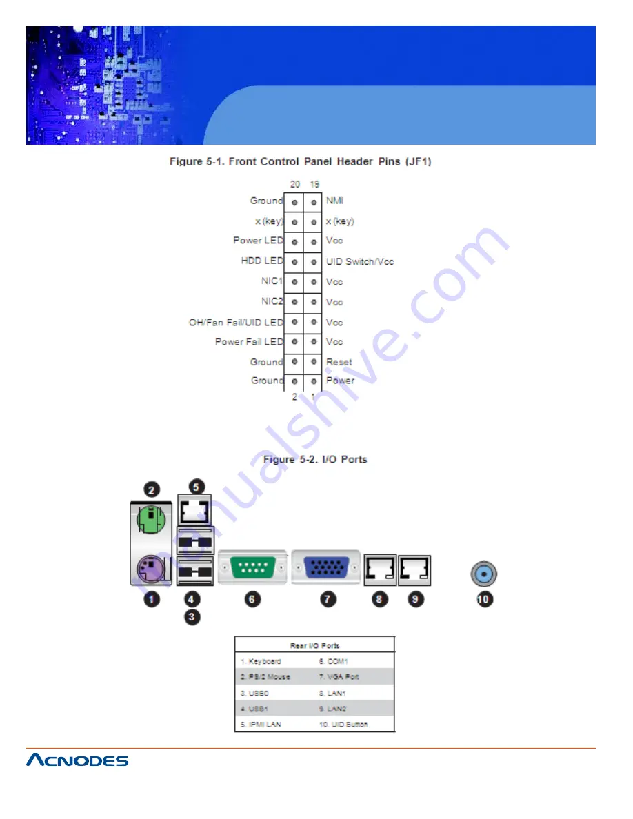
5-4 I/O Ports
The I/O ports are color coded in conformance with the PC 99 specification. See Figure 5-2 below for the
colors and locations of the various I/O ports.


