


- 29 -
06/ Control By Universal DMX Controller
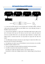
6.1 DMX512 Connection
1. At last unit, the DMX cable has to be terminated with a terminator. Solder a 120-ohm
1/4W resistor between pin 2(DMX-) and pin 3(DMX+) into a 3-pin XLR-plug and plug it in
the DMX-output of the last unit.
2. Connect the unit together in a “daisy chain” by XLR plug cable from the output of the
unit to the input of the next unit. The cable can only be used in series and cannot be
connected in parallel. DMX 512 is a very high-speed signal. Inadequate or damaged cables,
soldered joints or corroded connectors can easily distort the signal and shut down the
system.
3. The DMX output and input connectors are pass-through to maintain the DMX circuit,
when one of the units’ power is disconnected.
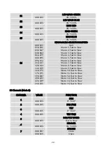
4. Each lighting unit needs to have a DMX address to receive the data by the controller.
The address number is between 1-512.
5. The end of the DMX 512 system should be terminated to reduce signal errors.
6. 3 pin XLR connectors are more popular than 5 pins XLR.
3 pin XLR: Pin 1: GND, Pin 2: Negative signal (-), Pin 3: Positive signal (+)
5 pin XLR: Pin 1: GND, Pin 2: Negative signal (-), Pin 3: Positive signal (+), Pin4, Pin5 not
used.
Summary of Contents for STORM
Page 1: ......
Page 11: ... 10 Installation for version without fixed clamps ...
Page 12: ... 11 Installation for version with fixed clamps ...
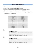
Page 56: ... 55 LED LED WASH MACRO SELECTION ...
Page 57: ... 56 ...
Page 58: ... 57 ...
Page 59: ... 58 ...
Page 60: ... 59 RING MACRO SELECTION A ...
Page 61: ... 60 ...
Page 62: ... 61 ...
Page 63: ... 62 ...
Page 64: ... 63 ...
Page 65: ... 64 ...
Page 66: ... 65 RING MACRO SELECTION B ...
Page 67: ... 66 ...
Page 68: ... 67 ...
Page 69: ... 68 ...
Page 76: ......


