background image


RDM FUNCTIONS 

Select the MANUFACTURER menu to display the manufacturer of the fixture. 
Select the SOFTWARE VERSION menu and the program version number of the fixture will be 
displayed. 
Select the DMX START ADDRESS menu to change the DMX 512 address (001-512). 
Select the DEVICE MODEL DESCRIPTION menu to display the model of the fixture. 
Select the DEVICE LABEL menu to change the model of the fixture. 
Select the DMX PERSONALITY menu to set the channel mode of the fixture (108/15/11/3 channel). 
Select the DMX PERSONALITY  DESCRIPTION  menu to display the current channel mode of the 
fixture. 
Select the DEVICE HOURS menu to display the running time of the fixture. 
 

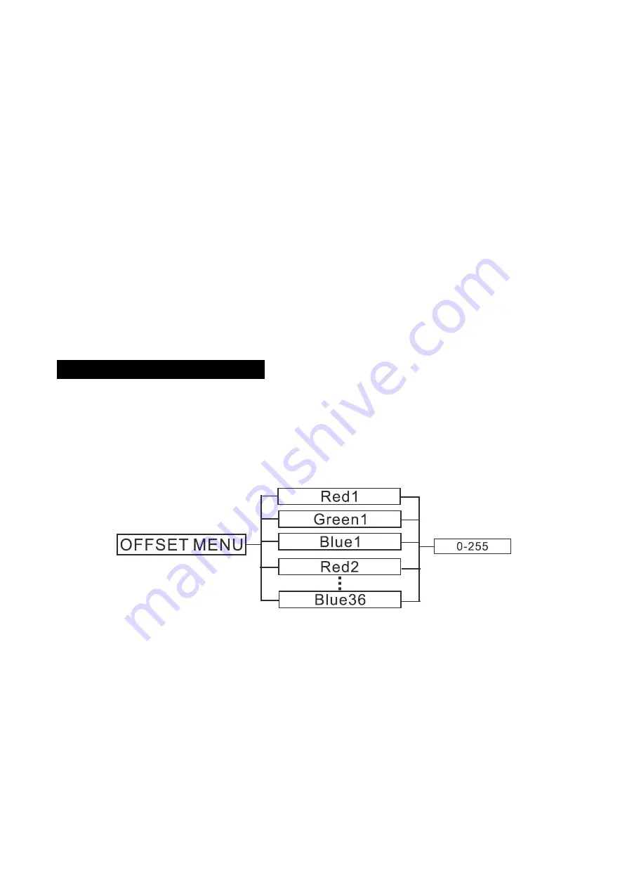
5.2 Home Position Adjustment   

Press the MENU button into menu mode, then press the ENTER button for about 3 seconds into 
offset mode to adjust the home position. Select the function by the  ENTER button. Use the 
UP/DOWN button to choose the submenu, press the ENTER button to store and automatically 
return to the last menu. Press MENU button to exit. 


Red1


Enter offset mode, select 

Red1

, press the

 ENTER

 button to confirm, the present position will blink 

on the display, use the 

UP

/

DOWN 

button to offset the value from 0 to 255, press the

 ENTER

 button 

to store. Press


the

 MENU

 button to exit. 

Green1


Enter offset mode, select 

Green1

, press the 

ENTER

 button to confirm, the present position will blink 

on the display, use the 

UP

/

DOWN

 button to offset the value from 0 to 255, press the

 ENTER

 button 

to store. Press the

 MENU

 button to exit. 


12B 

Summary of Contents for ANIMA C

Page 1: ......

Page 2: ...5 4 Installation 5 5 How To Set The Unit 7 5 1 Main Function 7 5 2 Home Position Adjustment 12 6 Control By Universal DMX Controller 13 6 1 DMX512 Connection 13 6 2 Address Setting 14 6 3 DMX512 Configuration 15 7 Error Information 25 8 Troubleshooting 25 9 Fixture Cleaning 26 1B ...

Page 3: ...t no ventilation slots are blocked otherwise the unit will be overheated Before operating ensure that the voltage and frequency of power supply match the power requirements of the unit It s important to ground the yellow green conductor to earth in order to avoid electric shock Minimum ambient temperature TA 0 Maximum ambient temperature TA 40 DO NOT connect the device to any dimmer pack Make sure...

Page 4: ...y yourself Repairs carried out by unskilled people can lead to damage or malfunction Please contact the nearest authorized technical assistance center if needed Disconnect the mains power if the fixture is has not been used for a long time DO use the original packing materials before transporting it again DO NOT look directly at the light while the LED is on DO NOT start on the unit without LED en...

Page 5: ...ector in out Protection Rating IP20 Features Compact design light in weight Multiple units can be split jointed horizontally with connecting board LED can be controlled pixel by pixel delivering versatile effects Dimensions Weight 500x85x500mm 9 3kgs 19 7 x3 3 x19 7 in 20 5lbs Photometrics Diagram 4B ...

Page 6: ...the next units 5 pin XLR is optional 5 POWERCON IN Connects to supply power 6 POWERCON OUT Connects to the next fixture 4 Installation Always ensure that the unit is firmly fixed to avoid vibration and slipping while operating and make sure that the structure to which you are attaching the unit is secure and is able to support a weight of 10 times of the fixtures weight Always use a safety cable t...

Page 7: ...k the clamp C on the truss 3 Multi machine assembly As shown in the figure loosen the screws A of the splicing plate of the fixture Then join the fixtures together in pairs and move the splicing plate tighten the screws and fix them on the two fixtures Fix the connecting plate B on the four corners of the fixtures by using screws and nuts so that the fixtures are spliced and fastened to each other...

Page 8: ...n until the required function is shown on the monitor Select the function by the ENTER button Use the UP DOWN button to choose the submenu press the ENTER button to store and automatically return to the last menu Press the MENU button or let the unit idle 30 seconds to exit menu mode The main functions are shown below 7B ...

Page 9: ...inues to obey the last command it received Via DMX if DMX signal stops Blackout fixture blacks out if DMX signal stops or Manual the fixture will automatically read the DMX value in the Manual Test menu for operation after selecting this mode press the ENTER button to store Press the MENU button back to the last menu or let the unit idle 30 seconds to exit menu mode View DMX Value To select View D...

Page 10: ... select Red Green Blue Red1 Green1 Blue1 or Red36 Green36 Blue36 press the ENTER button to store Press the MENU button back to the last menu or let the unit idle 30 seconds to exit menu mode Display Settings To select Display Settings press the ENTER button to confirm use the UP DOWN button to select Display Invert Temperature Unit Display Warning or Fixture Language Display Invert Select Display ...

Page 11: ...anual Test press the ENTER button to confirm use the UP DOWN button to select Mode Clear Red1 Green1 Blue1 Red36 Green36 Blue36 or Red Green Blue Shutter Dimmer press the ENTER button to confirm use the UP DOWN button to adjust the value from 0 to 255 press the ENTER button to store Press the MENU button back to the last menu or let the unit idle 30 seconds to exit menu mode Information To select ...

Page 12: ...s the ENTER button to confirm RDM UID will show on the display press the MENU button back to exit Error Logs Select Error Logs press the ENTER button to confirm Use the UP DOWN button to select Fixture Errors or Reset Error Log press the ENTER button to store Select Reset Error Log press the ENTER button to confirm Use the UP DOWN button to select No or Yes press the ENTER button to store Select Y...

Page 13: ...e of the fixture 5 2 Home Position Adjustment Press the MENU button into menu mode then press the ENTER button for about 3 seconds into offset mode to adjust the home position Select the function by the ENTER button Use the UP DOWN button to choose the submenu press the ENTER button to store and automatically return to the last menu Press MENU button to exit Red1 Enter offset mode select Red1 pres...

Page 14: ...255 press the ENTER button to store Press the MENU button to exit Green36 Enter offset mode select Green36 press the ENTER button to confirm the present position will blink on the display use the UP DOWN button to offset the value from 0 to 255 press the ENTER button to store Press the MENU button to exit Blue36 Enter offset mode select Blue36 press the ENTER button to confirm the present position...

Page 15: ...signal errors 6 3 pin XLR connectors are more popular than 5 pins XLR 3 pin XLR Pin 1 GND Pin 2 Negative signal Pin 3 Positive signal 5 pin XLR Pin 1 GND Pin 2 Negative signal Pin 3 Positive signal Pin4 Pin5 not used 6 2 Address Setting If you use a universal DMX controller to control the units you have to set DMX address from 1 to 512 so that the units can receive DMX signal Press the MENU button...

Page 16: ...econds then the corresponding function will take into effect 108 Channels Mode 1 CHANNEL VALUE FUNCTION 1 000 255 RED1 0 100 2 000 255 GREEN1 0 100 3 000 255 BLUE1 0 100 4 000 255 RED2 0 100 5 000 255 GREEN2 0 100 6 000 255 BLUE2 0 100 106 000 255 RED36 0 100 107 000 255 GREEN36 0 100 108 000 255 BLUE36 0 100 15 Channels Mode 2 CHANNEL VALUE FUNCTION 1 000 255 RED RING 1 0 100 2 000 255 GREEN RING...

Page 17: ...028 031 032 036 037 040 041 045 046 049 050 054 055 058 059 063 064 067 068 072 073 076 077 081 082 085 086 090 091 094 095 099 100 103 104 108 109 112 113 117 118 121 122 126 127 130 131 135 136 139 140 144 CTO 8000K 2500K Close 8000K 7900K 7800K 7700K 7600K 7500K 7400K 7300K 7200K 7100K 7000K 6900K 6800K 6700K 6600K 6500K 6400K 6300K 6200K 6100K 6000K 5900K 5800K 5700K 5600K 5500K 5400K 5300K 52...

Page 18: ...0 034 035 039 040 044 045 049 050 054 055 059 060 064 065 069 070 074 075 079 080 084 085 089 090 094 095 099 100 104 105 109 110 114 COLOR MACRO Open LEE 790 Moroccan Pink LEE 157 Pink LEE 332 Special Rose Pink LEE 328 Follies Pink LEE 345 Fuchsia Pink LEE 194 Surprise Pink LEE 181 Congo Blue LEE 071 Tokyo Blue LEE 120 Deep Blue LEE 079 Just Blue LEE 132 Medium Blue LEE 200 Double CT Blue LEE 161...

Page 19: ...n Clockwise Rotation Fast to Slow Stop Counter clockwise Rotation Slow to Fast Open Random Color Fast Random Color Medium Random Color Slow Open 12 000 007 008 015 016 131 132 139 140 181 182 189 190 231 232 239 240 247 248 255 STROBE Close Opne Strobe from Slow to Fast Open Fast Close Slow Open Open Fast Open Slow Close Open Random Strobe Open 13 000 255 DIMMER 0 100 14 000 255 DIMMER FINE 15 000...

Page 20: ...0 100 2 000 255 GREEN 0 100 3 000 255 BLUE 0 100 4 000 001 004 005 009 010 013 014 018 019 022 023 027 028 031 032 036 037 040 041 045 046 049 050 054 055 058 059 063 064 067 068 072 073 076 077 081 082 085 086 090 091 094 095 099 100 103 CTO 8000K 2500K Close 8000K 7900K 7800K 7700K 7600K 7500K 7400K 7300K 7200K 7100K 7000K 6900K 6800K 6700K 6600K 6500K 6400K 6300K 6200K 6100K 6000K 5900K 5800K 1...

Page 21: ...00K 4800K 4700K 4600K 4500K 4400K 4300K 4200K 4100K 4000K 3900K 3800K 3700K 3600K 3500K 3400K 3300K 3200K 3100K 3000K 2900K 2800K 2700K 2600K 2500K 5 000 009 010 014 015 019 020 024 025 029 030 034 035 039 040 044 045 049 050 054 055 059 060 064 065 069 COLOR MACRO Open LEE 790 Moroccan Pink LEE 157 Pink LEE 332 Special Rose Pink LEE 328 Follies Pink LEE 345 Fuchsia Pink LEE 194 Surprise Pink LEE ...

Page 22: ...ime Green LEE 100 Spring Yellow LEE 104 Deep Amber LEE 179 Chrome Orange LEE 105 Orange LEE 021 Gold Amber LEE 778 Millennium Gold LEE 135 Deep Gold Amber LEE 164 Flame Red Open Clockwise Rotation Fast to Slow Stop Counter clockwise Rotation Slow to Fast Open Random Color Fast Random Color Medium Random Color Slow Open 6 000 014 015 047 048 095 096 135 136 175 176 215 216 255 MODE Blackout Full On...

Page 23: ...ct 20 Effect 21 Effect 22 Effect 23 Effect 24 Effect 25 Effect 26 Effect 27 Effect 28 Effect 29 Effect 30 Effect 31 7 2 000 025 026 048 049 071 072 094 095 117 118 140 141 163 164 186 187 209 210 232 233 255 NUMBER 1 to 9 No Function Number 0 Number 1 Number 2 Number 3 Number 4 Number 5 Number 6 Number 7 Number 8 Number 9 7 3 000 021 022 030 031 039 040 048 049 057 058 066 067 075 076 084 085 093 ...

Page 24: ...021 022 030 031 039 040 048 049 057 058 066 067 075 076 084 085 093 094 102 103 111 112 120 121 129 130 138 139 147 148 156 157 165 166 174 175 183 184 192 193 201 202 210 211 219 220 228 229 237 238 246 247 255 LETTER a to z No Function Letter a Letter b Letter c Letter d Letter e Letter f Letter g Letter h Letter i Letter j Letter k Letter l Letter m Letter n Letter o Letter p Letter q Letter r ...

Page 25: ...40 049 050 059 060 069 070 079 080 089 090 099 100 109 110 119 120 129 130 139 140 179 180 189 190 199 200 209 210 219 220 229 230 255 SPECIAL FUNCTION Null Dimmer Curve Linear Dimmer Curve Square Law Dimmer Curve Inv SQ Law Dimmer Curve S Null Null Null Null Null Null Null Null Dimmer Speed Fast Dimmer Speed Smooth Null Null Null Null 3 Channels Mode 4 CHANNEL VALUE FUNCTION 1 000 255 RED 0 100 2...

Page 26: ...k the connect power 2 Measure the mains voltage on the main connector 3 Check the power on LED to see if it can be light up or not B Not responding to DMX controller 1 Check DMX connectors cables to see if they are linked properly 2 Check the address settings and DMX polarity 3 If you have intermittent DMX signal problems check the pins on connectors or on PCB of the unit or the previous one 4 Try...

Page 27: ...ight output Cleaning frequency depends on the environment in which the fixture operates damp smoky or particularly dirty surrounding can cause greater accumulation of dirt on the unit s optics Clean with soft cloth and use normal glass to clean liquid Always dry the parts carefully Clean the external optics at least every 20 days 26B ...

Page 28: ...Innovation Quality Performance ...

Reviews: