ASD SERIES INSTALLATION AND OPERATION MANUAL
20
14.1.2
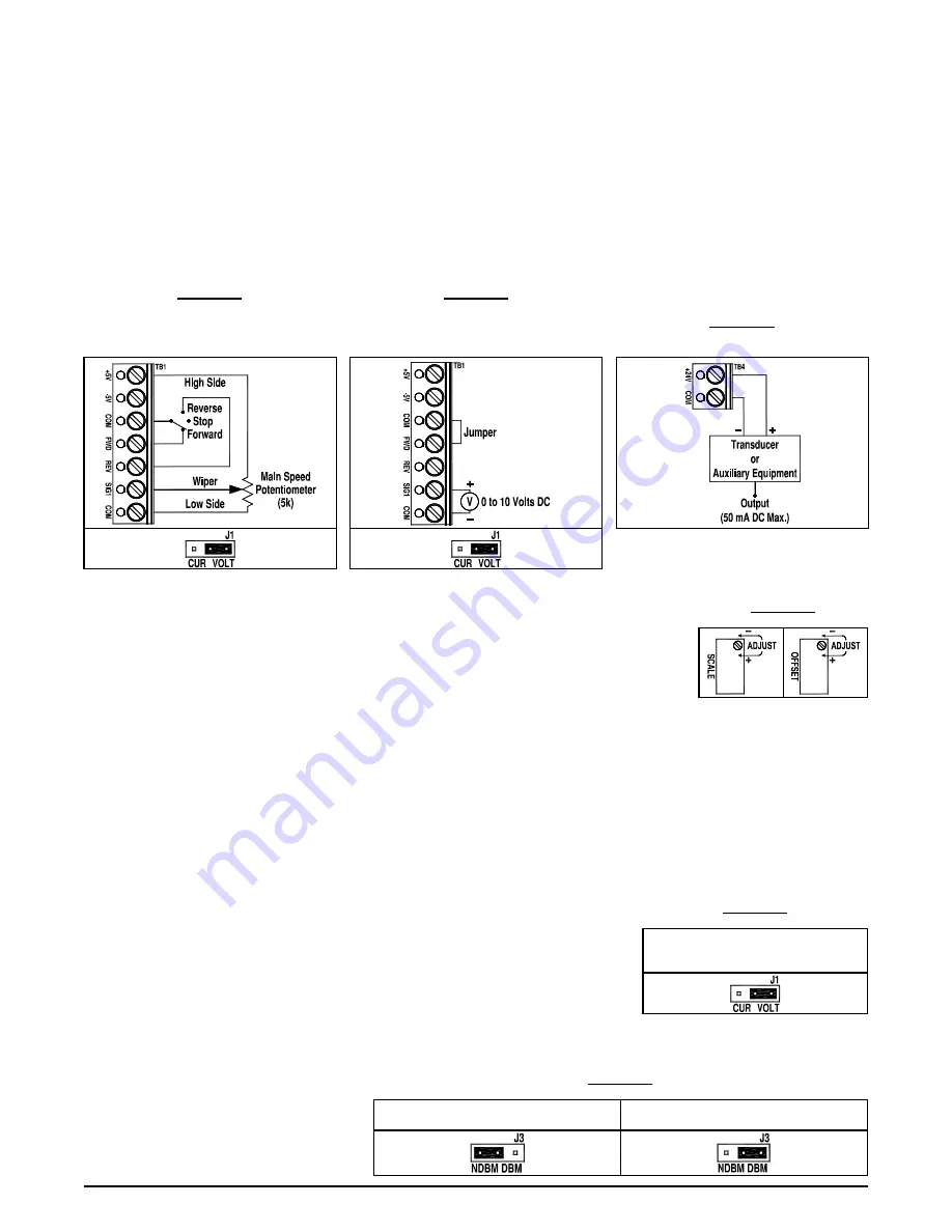
– MAIN SPEED POTENTIOMETER CONNECTION
The Main Speed Potentiometer (
5 kΩ), that is installed on the front cover is wired to the Signal Isolator. The potentiometer is connected as
follows: high side to Te5V, wiper to Terminal SIG1, and low side to Terminal COM. See Figure 34.
14.1.3
– VOLTAGE FOLLOWING SIGNAL INPUT CONNECTION
A 0 to 10 Volt DC analog signal input can be used to control motor speed. The drive output will linearly follow the analog signal input. Wire the
signal input positive lead (+) to Terminal SIG1 and the negative lead (-) to Terminal COM. See Figure 35.
Note:
Use the SCALE Trimpot to scale the signal input, as described in Section 14.2.1. Do not use the MAX Trimpot on the drive.
14.1.4
– 24 VOLT DC POWER SUPPLY CONNECTION FOR TRANSDUCER OR AUXILIARY EQUIPMENT
The 24 Volt DC Power supply can be used to power a transducer or auxiliary equipment. maximum current rating is 50 mA DC. See Figure 36.
FIGURE 34
Unidirectional
Main Speed Potentiometer with
Forward-Stop-Reverse Switch Connection
(J1 Set to "VOLT" Position)
FIGURE 35
Voltage Following
Signal Input Connection
(Shown in Forward Operation)
(J1 Set to "VOLT" Position)
FIGURE 36
24 Volt DC Power Supply Connection
for Transducers or Auxiliary Equipment
14.2 - TRIMPOT ADJUSTMENTS
The Signal Isolator contains trimpots which are factory set for most applications. The Signal Isolator is factory
set for Voltage Following Operation to run the motor from zero speed to full speed with a 0 to 5 Volt DC analog
signal input. For Current Following Operation, see Section 5.2. Some applications may require readjustment of
the trimpots in order to tailor the drive for a specific application.
14.2.1
– SCALE TRIMPOT (SCALE)
The SCALE Trimpot is factory set to run the motor at full speed with a 10 Volt DC analog signal input. For a higher analog signal input (25 Volt
DC maximum), rotate the SCALE Trimpot counterclockwise. For a lower analog signal input (2.5 Volt DC min.), rotate the SCALE Trimpot
clockwise. See Figure 37.
Note:
The MAX Trimpot on the drive has been factory set to an Upper Frequency Limit of 60 Hz (50 Hz, for 50 Hz motors). If the application
requires a slightly higher maximum frequency, rotate the MAX Trimpot on the drive to full clockwise position.
14.2.2
– OFFSET TRIMPOT (OFFSET)
The OFFSET Trimpot is used to recalibrate the drive for Current Following Operation. The Signal Isolator will run the motor from zero speed to
full speed with a 4
– 20 mA DC analog signal input. For a higher minimum speed setting, rotate the OFFSET trimpot clockwise. For a lower
minimum speed setting, rotate the OFFSET Trimpot counterclockwise. See Figure 37.
14.3
– SETTING SELECTABLE JUMPERS
Jumpers J1 and J3 are used to set the signal input and source. Jumper J2 is set to the "AN" position
for analog signal input. Jumper J4 is set to the "LED" position for the IND LED.
14.3.1
– SIGNAL INPUT SELECTION (J1)
Set Jumper J1 to the "VOLT" position for Main Speed Potentiometer Operation or for Voltage
Following Signal input. See Figure 38.
14.3.2
– SIGNAL SOURCE SELECTION (J3)
Set Jumper J3 to the "NDBM" position for Main Speed Potentiometer Operation. Set Jumper J3 to the "DBM" position for voltage Following
Operation. See Figure 39.
FIGURE 37
TRIMPOT ADJUSTMENTS
FIGURE 38
JUMPERS J1 SETTING
Jumper J1 set to the "VOLT" Position
for Main Speed Potentiometer
or Voltage Following Signal Input
FIGURE 39
JUMPER J3 SETTINGS
Jumper J3 set to the "NDBM" Position
for Main Speed Potentiometer Operation
Jumper J3 set to the "DBM" Position
for Voltage Following Operation


