ASD SERIES INSTALLATION AND OPERATION MANUAL
19
FEATURES
▪ Isolated Switching:
Provides isolation for PLC open collector or contact switching.
▪ Isolated 5 Volt DC Power Supply:
Used for Main Speed Potentiometer operation (25 mA DC max.).
▪ Isolated 24 Volt DC Power Supply:
Used to power a transducer or auxiliary equipment (50 mA DC max.).
▪ Trimpot Adjustments (Multi-Turn):
Signal Scaling (SCALE) and Signal Offset (OFFSET).
▪ Power On LED:
Provides indication that power is applied.
▪ IND LED:
Blinks green to provide indication that the microprocessor is functioning properly.
▪ Jumper J1 (Signal Input Selection):
"VOLT" position for voltage signal input. "CUR" position for current signal input.
▪ Jumper J2 (Signal Type Selection):
"AN" position for analog signal input. "PWM" position is for PWM signal input.
▪ Jumpers J3 (Signal Source Selection):
"NDBM" position for Main Speed Potentiometer Operation (0
– 5 Volts DC). "DBM" position for
Voltage Following Operation (0
– 10 Volts DC).
▪ Jumpers J4:
Installed in the "LED" position for the IND LED.
TABLE 6
SIGNAL ISOLATOR GENERAL PERFORMANCE SPECIFICATIONS
Parameter
Specifications
Factory Setting
Signal Scaling Trimpot (SCALE) Input Voltage Range (Volts DC)
0 to 2.5 thru 0 to 25
0 to 5
Signal Offset Trimpot (OFFSET) Range (% of SCALE Trimpot Setting)
0
– ±40
0
Input Current Range (mA DC)
4
– 20
—
Forward and Reverse Input Switch Types
Dry Contact or Open Collector
—
5 Volt DC Power Supply Maximum Load Current Rating (mA DC)
25
—
24 Volt DC Power Supply Maximum Load Current Rating (mA DC)
50
—
Potentiometer Operation (kΩ)
5
—
Input/Output Linearity (%)
0.1
—
Thermal Drift (millivolts per °C)
0.4
—
Operating Temperature Range (°C / °F)
0
– 40 / 32 – 104
—
Operating Humidity Range (% Relative, Non-Condensing)
0
– 95
—
Storage Temperature (°C / °F)
-25
– +85 / -13 – +185
—
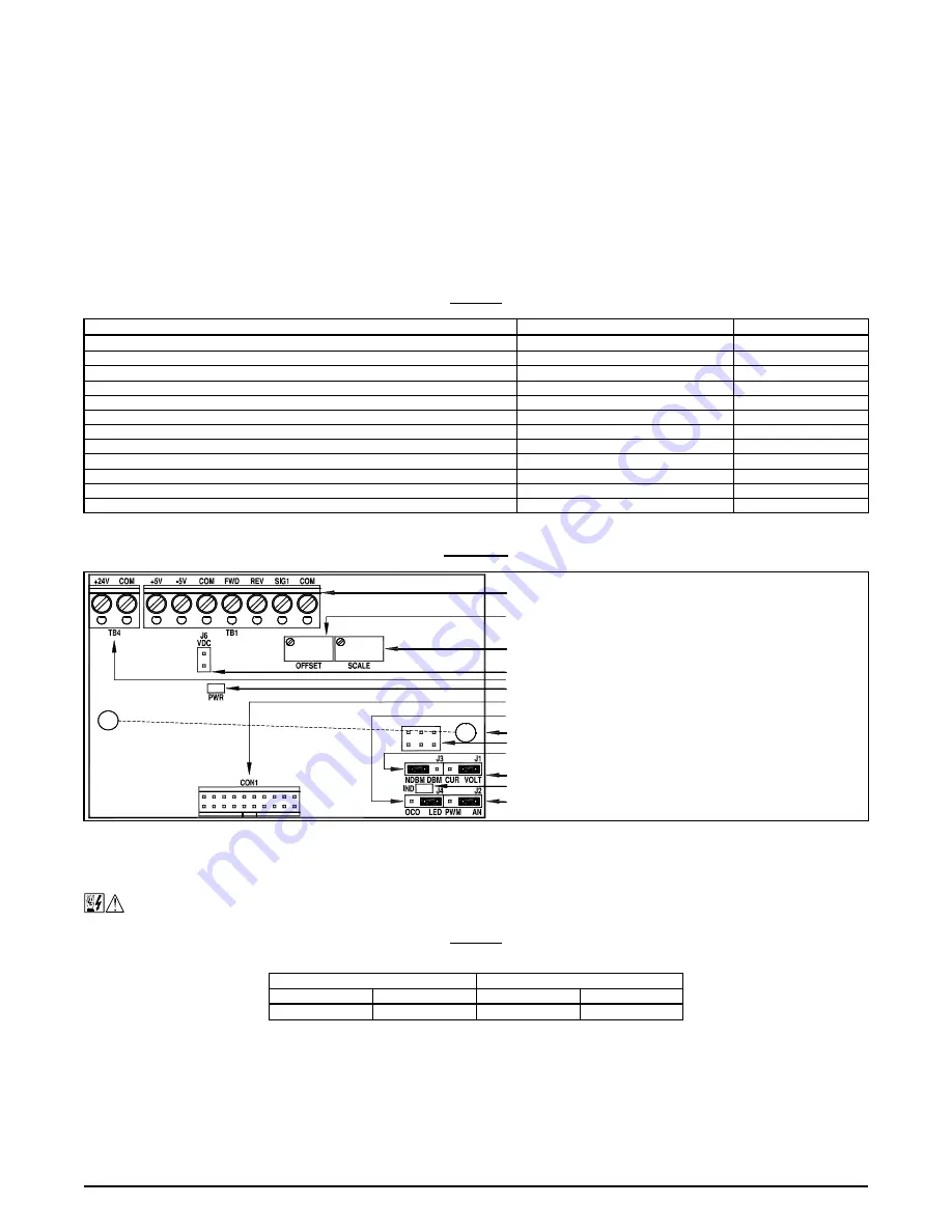
FIGURE 33
SIGNAL ISOLATOR LAYOUT
14.1
– WIRING INSTRUCTIONS
All connections are made on Terminal Blocks TB1 and TB4 on the Signal Isolator. See Table 7.
WARNING! Disconnect the main power before making connections to the drive or Signal Isolator.
TABLE 7
SIGNAL ISOLATOR TERMINAL BLOCKS TB1 AND TB4
WIRE SIZE AND TIGHTENING TORQUE SPECIFICATIONS
Maximum Wire Size (Cu)
Recommended Tightening Torque
AWG
mm
2
in-lbs
kg-cm
16
1.3
3.5
4
14.1.1
– DIRECTION SELECTION
Bidirectional Speed Operation:
Wire a Forward-Stop-Reverse Switch to Terminals FWD, COM, and REV. See Figure 34 on page 20.
Unidirectional Speed Operation:
For Forward Speed Operation, wire a jumper between Terminals COM and FWD. For Reverse Speed
Operation wire a jumper between Terminals COM and REV. See Figure 35 on page 20.


