5
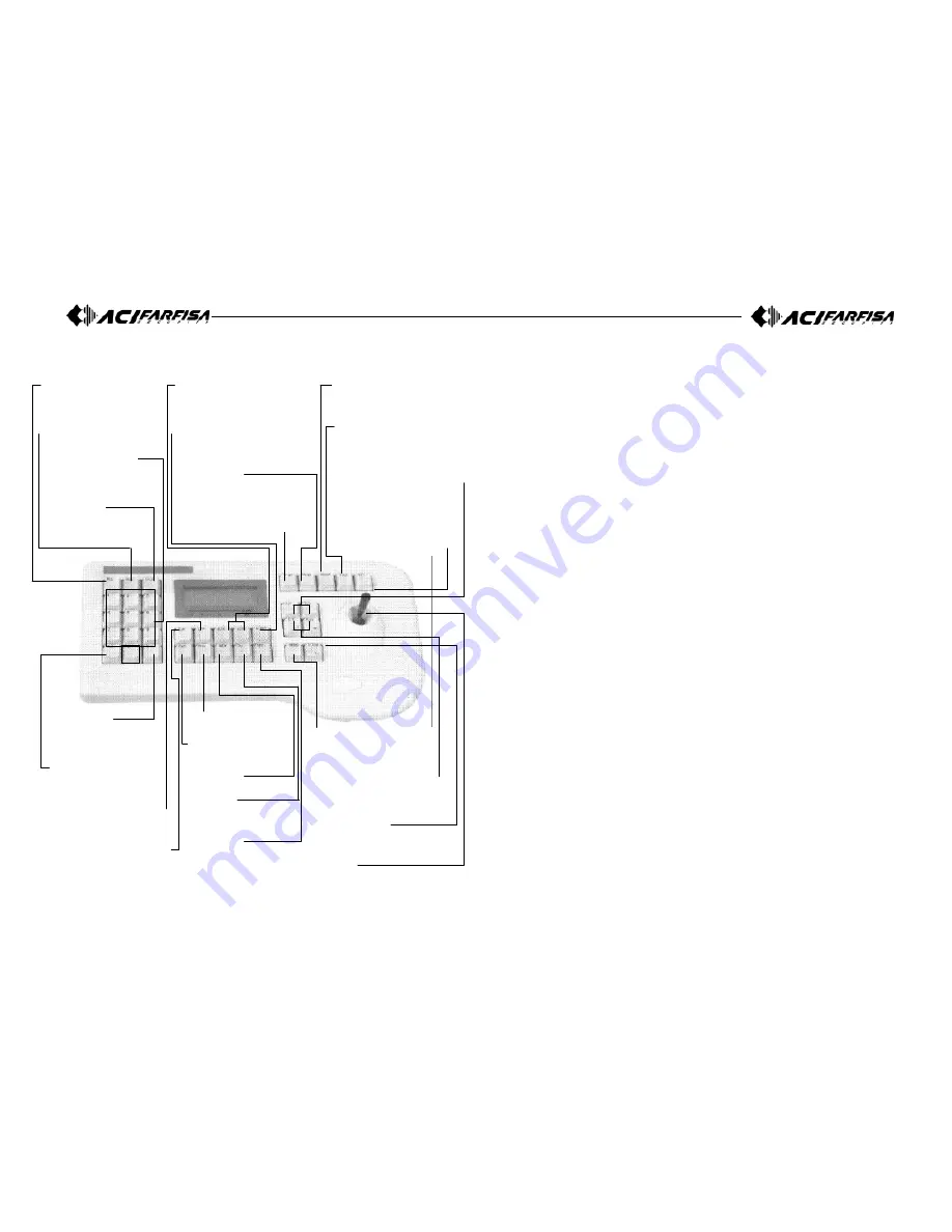
4. Appearance and Function Key
1) Controller function button
2) Setting method of Junction box
- Camera controls 1
This is the input and output terminal. Connect 485+ to data + and 485–
to data –.
When you communicate with RS-485, the left switch of Junction box
must be set backward.
When you communicate with RS-422, the left switch of Junction box
must be set forward.
- Camera controls 2
Same as camera control 1.
- Sub Keyboard
Sub keyboard must be used only with sub keyboard and linked with
same line.
n communicating with RS-485, the right switch of Junction box must be
set backward (DC Jack direction).
In communicating with RS-422, the right switch of Junction box must
be set forward.
- Junction box’ s input and output terminal
This terminal informs you that the data in/out in electronic transmission
of long distance, can be used as a data in/out transmission signal in
communicating with RS-485.
In transmitting from keyboard to camera, you have to exteriorly pull up
because, the camera receive reversely, such as when you send “high”,
you get “low”, so pull up outside.
“Exteriorly pull up” is?
Don’ t put pull up resistance to collector of Transistor and make ’The
line driver’ pull up, then it can function normally.
Ascertain
The check voltage of GND and RTS should be over 5V.
Caution
Sub keyboard can function only in general control.
Under the situation that alarm is on in main keyboard, you can hear
alarm sound when something is in disorder.
Data line using for control of camera only connected to main Junction
box, can makes sub keyboard function.
ALL Button
Simultaneous on/off of
cameras, lights and AUX1.
(only for receiver unit)
GROUP Button
This button is used to monitor
the preset pionts sequentially.
TOUR Button
This button is used to monitor
the groups sequentially.
SET Button
This button is used to start the
setting mode of various function.
Z/I (Zoom In), Z/O (Zoom Out) Button
Operate the zoom control of
camera.
AUX (Auxiliary) Buttons
These buttons are used to control
of Auto-Pan (AUX1) and other unit
(AUX2). (Only for receiver unit).
ALARM Buttons
This button is used to on/off of
registered video motion detection.
SWING Button
This button is used to move the
camera between two preset points.
P-Set (Preset) Button
This button is used to input and
confirmation of preset points. (Max.
64 positions each camera).
RUN Button
#
Numeric Keypad (0-9)
These keys are used to
make input for settings and
other functions.
HOLD Button
#
ENTER Button
This button is used to save
when camera or program is
inputted
CLR (Clear) Button
This button is used to clear
wrong number of function.
L/P (Light Power) Button
This button is used to on/off the
light. (only for receiver unit)
C/P (Camera Power) Button
This button is used to on/off the
camera. (only for receiver unit)
MON (Monitor) Button
#
CAM (Camera) Button
This button is used to
select a camera.
View Button
#
ON Button
This button is used to
execute the functions.
OFF Button
This button is used to
stop the functions.
MENU Button
This button is used to set up
the function with number button
(Refer to function guide).
F/F (Focus Far), F/N (Focus Near)
Button
Operate the focus control of
camera.
STATUS Button
This button is used to freeze
on/off of Video-out signal.
Joystick
This stick is used to control
pan/tilt and move the cursor in
the OSD menu.
#: This button is allowed to be used only for the control of
matrix system. Not allowed for speed dome camera control.


