33
Purchase MSP430 TOOL the contact way: Beijing zhongguancun trade electronics co., LTD.,
Contact person: Li Shaolin, Contact phone number: 13621123062,
Product drive default is VCP, before buying, please ask them to upgrade to the CDC version.
2.Install driver
When insert the msp430 tool to PC, you need to install the driver. we suggest use windows 10 64bit
3. TI micro-controllers FW update
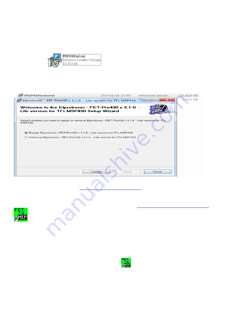
3.1.1 Double-click
to install ISP program.the version is V3.1-0.
3.1.2 TI micro-controllers FW update
This chapter describes how to flash new code into the two TI-MSP430 micro-controllers on the NVIDIA G-SYNC
module and base board. These two micro-controllers take care of handling the button presses and the LED control of
the monitor. One of the two micro-controllers is located on the G-sync module, and the second micro-controllers is
located on the base board.
3.1.3 Required Hardware
The hardware required to update the code on the two micro-controllers is a TI-MSP430 USB debug interface.
This device can be ordered from TI at
http://www.ti.com/tool/msp-fet430uif
.
3.1.4 Required Software
In order to load the binary code into the flash memories for the micro-controllers, we use the Elpotronic FET-Pro430
Lite software. This software is free to use and can be downloaded from
http://www.elprotronic.com/download.html
.
3.1.0 Updating the base board micro-controller
Connect the cable that came with the TI MSP-FET430UIF in the way indicated in the picture above. Make sure that
pin1 of the ribbon cable header that connects to the base board. Connect the USB cable connected to the MSP-
FET430UIF to the computer that has the FET-Pro430 Lite software installed. At this time Windows should have a
popup that says “Installing New Device Driver Software”, which should finish without any issues and install the USB
driver for the MSP-FET430UIF.
3.1.5 Starting the Software and Flashing the New Code
Double click the shortcut to the “Lite FET-Pro430 Elprotronic”
icon created on the desktop earlier when installing
the software. This should bring up the following window:
Summary of Contents for X25
Page 9: ...9 ...
Page 11: ...11 ...
Page 12: ...12 S8 Remove the screws to remove the boards Disconnect all of the cables ...
Page 13: ...13 S9 Remove the screws to remove the main board and the G sync board ...
Page 16: ...16 S4 Prepare the panel assemble as below picture ...
Page 18: ...18 ...
Page 19: ...19 S8 Connect the pins and assemble it ...
Page 20: ...20 S9 Prepare a STAND BASE ASSY to assemble it ...
Page 23: ...23 The software must install it to C disk the path C altera 16 0 older ...
Page 24: ...24 1 4 Flash Bitstream if necessary 1 4 1 Install USB Blaster driver ...
Page 25: ...25 ...
Page 27: ...27 ...
Page 28: ...28 1 4 4 Click on the following figure to open the file to be burned ...
Page 29: ...29 ...
Page 30: ...30 1 4 5 According to the figure below the digital sequence began to burn FPGA ...
Page 31: ...31 ...
Page 42: ...42 If appear this error please to update the version of software Tool software update steps ...
Page 43: ...43 After tool software update success will appear this message Note How to remove the tool ...
Page 46: ...46 ...
Page 50: ...50 OSD FW Version ...


