Chapter 3
47
9.
Remove the screw (A) that secures the power supply to the chassis.
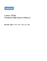
10.
Remove the three screws (A) that secure the power supply to the rear panel.
Screw (Quantity)
Color
Torque
Part No.
#6-32 L5 BZN (1)
Black
5.5 to 6.5 kgf-cm
86.00J07.B60
Screw (Quantity)
Color
Torque
Part No.
#6-32 L5 BZN (3)
Black
5.5 to 6.5 kgf-cm
86.00J07.B60
Summary of Contents for X1200 ED5200A - Aspire
Page 8: ...viii ...
Page 38: ...30 Chapter 2 ...
Page 56: ...48 Chapter 3 11 Lift the power supply module out of the chassis ...
Page 58: ...50 Chapter 3 8 Gently pull the DIMM upward to pull it away from the chassis ...
Page 60: ...52 Chapter 3 8 Gently pull the card to remove it from the mainboard ...
Page 76: ...68 Chapter 4 ...
Page 77: ...Chapter 5 69 System Block Diagram System Block Diagram and Board Layout Chapter 5 ...
Page 80: ...72 Chapter 5 ...
Page 82: ...74 Chapter 6 Aspire ASX1200 ASX3200 Exploded Diagram ...