Acer V551 (new) CRT Monitor Service Guide
Chapter 2 Circuit Operation Theory
19
Confidence and Property
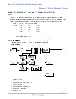
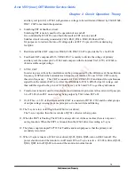
auxiliary coil (pin 8-9) of T601 will generate a voltage to be rectified and filtered by C608, D608,
D607, C607 to maintain the operation.
4. Switching FET & Snubber circuit.
Switching FET is mainly used for the operation of on and off.
It is controlled by IC601.We can obtain the result of FET turn on and off.
Snnbber circuit is mainly consisted of C624, R619, D614, D610, R604 and C613.
It's purpose is to restrain the turn off voltage spike of FET. To prevent it from destroying
for
Q602.
5. Rectifier and filter CKT comprises D608, C608, D607, C607 to provide the Vcc for IC601.
6. Feed back CKT comprises R616, VR601, R617 is mainly to divide the voltage of primary
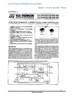
auxiliary coil, then enter pin 2 of 3842 and compare with the internal Vref (2.5V) of IC601 to
obtain a stable output voltage.
7. SYNC. CKT
In order to prevent from the interference on the picture caused by the difference of the oscillation
frequency of SPS and the horizontal scan frequency of monitor, We use SYNC. CKT to unify
these two frequency. This CKT is consisted of C616, ZD603, R612 and detect the synchronous
signal from the monitor FBT core. After the differential of C616, ZD603 clips it's voltage. and
then add this signal to the pin 4 of UC3842 by way of 612 and C615 to get the synchronous.
8. Transformer is mainly used for transformer and isolation it's principle is the current will pass pin
1-4 of T601 when FET on and energy being output by T601 when FET off.
9. 10-12:This + 43.5V of Rectifier and filter CKT is consisted of D702, C703 and the other groups
of output voltage is using the same principle to do the rectifier and filtering
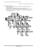
10. The V-sync is low or full high, then IC602 is not drived.
The V-sync is pulse, then the waveform of Q701 collector is sharp pulse.
11. When the ESP1 is floating, The IC602 is always drived. At the same time there is not power
saving function. When the ESP1 is Ground, then the IC602 drived according to V-sync.
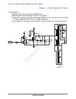
12. The photo coupler adopts TLP721F of Toshiba and main purpose is that the primary and
secondary is isolated.
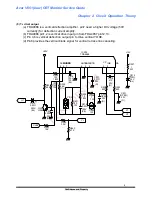
13. When V-sync is inactive, IC602 is not drived, Q603, Q604, Q605, turn on.Q602 turn off. The
power shut down and the monitor is in off mode .When V-sync is active . IC 602 is drived. Q603,
Q604, Q605 turn off. Q602 turn on and the monitor in normal mode.


