Acer V551 (new) CRT Monitor Service Guide
Chapter 2 Circuit Operation Theory
16
Confidence and Property
4. How to detect mode timing
Only when the mode timing input is stable, we can adjust the picture by the control panel, and the
major measurement of the mode timing inputs are horizontal and vertical sync.
(1) Vertical sync frequency measurement
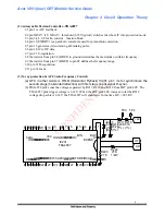
We use the base timer, it can generate a count during a fixed time, this fixed time is 12/12MHz and
we call it "Time base", so when the first vertical sync generated, we enable the base timer, and the
next vertical sync generated, we disable the base timer, and we only need to calculate how many
counts are during a vertical sync period.
The formula is
Vertical sync frequency
= FV
= 1 / Vertical sync period
= 1 / [ Counts * (Time base)]
==> Vertical sync frequency = 1000000 / Counts
(2) Horizontal sync frequency measurement
We use the event counter for calculating how many counts are during a long fixed time, because
the vertical sync period is longer than the horizontal sync period, we can enable the event counter
when the first vertical sync generated and disable the event counter when the next vertical sync
generated, this time, we can get the horizontal sync counts during a vertical sync period.
The formula is
Horizontal sync frequency
=
FH
= Horizontal sync counts / Vertical sync period
==> Horizontal sync frequency
= Horizontal sync Counts / Vertical sync period
5. What are the valid key functions for user
Total 4 keys for V551 control panel, "" & "select -" are the selection of controlled function
with LED change, and "" & "adjust -" are the selected item to increase & decrease volume.
Except the last basic key functions, the user can press "" & "adjust -" to recall the factory
preset data. Meanwhile it takes about 20 seconds for keeping no key pressed to store the adjusted
function into the user data.
6. How to execute the auto alignment function
The MCU supports the UART function, it has 2 I/O ports, one is the receiver, the other is the
transmitter, they are connected with an interface to PC and PC can execute alignment program by
RS232 communication to send the formatted data to the MCU for adjusting any adjustable
parameters of the picture and saving the adjusted values into EEPROM. By this way, we can get
the products with the same quality and reduce the manufacturing time.

