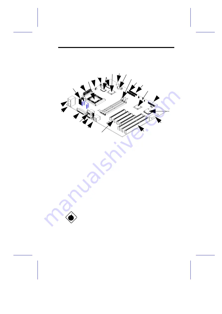
Figure 1-1 shows the board layout and the locations of the important
components.
1
Voltage Regulator with Heatsink
13
System Chipset PIIX4 82371AB
2
Power Connector
14
FDD Connector
3
CPU socket
15
Ultra I/O Chipset
4
Standby Power Connector
16
System BIOS Chip
5
Fan Connectors
17
ISA slots
6
256/512-KB pipelined-burst cache 18
PCI slots
7
System Chipset MTXC 82439TX
19
USB ports
8
Buzzer
20
COM 2 port
9
RTC battery
21
COM 1 port
10 DIMM sockets
22
Parallel port
11 IDE 2 connector
23
PS/2 keyboard connector
12 IDE 1 connector
24
PS/2 mouse connector
Figure 1-1
System Board Layout
The heatsink becomes very hot when the
system is on. NEVER touch the heatsink with
any metal or with your hands.
System Board
1-
3
1
2
3
4
6
8
9
1
1
1
2 1
3
1
4
2
2
1
0
2
1
1
9
1
8
1
7
1
6
1
5
2
4
2
0
2
3
5
7


