background image

EN-6

CONNECTOR PIN ASSIGNMENT

15-Pin Color Display Signal Cable                                        

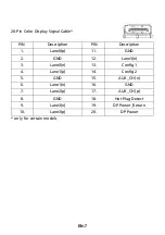
19-Pin Color Display Signal Cable                                    

PIN NO.

DESCRIPTION

PIN NO.

DESCRIPTION

1.

Red

9.

+5V

2.

Green

10.

Logic Ground

3.

Blue

11.

Monitor Ground

4.

Monitor Ground

12.

DDC-Serial Data

5.

DDC-return

13.

H-Sync

6.

R-Ground

14.

V-Sync

7.

G-Ground

15.

DDC-Serial Clock

8.

B-Ground

PIN

Meaning

PIN

Meaning

1.

TMDS Data2+

10.

TMDS Clock+

2.

TMDS Data2 Shield

11.

TMDS Clock Shield

3.

TMDS Data2-

12.

TMDS Clock-

4.

TMDS Data1+

13.

CEC

5.

TMDS Data1 Shield

14.

Reserved (N.C. on device)

6.

TMDS Data1-

15.

SCL

7.

TMDS Data0+

16.

SDA

8.

TMDS Data0 Shield

17.

DDC/CEC Ground

9.

TMDS Data0-

18.

+5V Power

19.

Hot Plug Detect

Summary of Contents for V277

Page 1: ...Acer LCD Monitor User s Guide...

Page 2: ...pondence concerning your unit should include the serial number model number and purchase information No part of this publication may be reproduced stored in a retrieval system or transmitted in any fo...

Page 3: ...w hours Information for your safety and comfort Safety instructions Read these instructions carefully Keep this document for future reference Follow all warnings and instructions marked on the product...

Page 4: ...These openings must not be blocked or covered The openings should never be blocked by placing the product on a bed sofa rug or other similar surface This product should never be placed near or over a...

Page 5: ...ding pin also provides good protection from unexpected noise produced by other nearby electrical devices that may interfere with the performance of this product Use the product only with the supplied...

Page 6: ...osphere are often but not always marked They include below deck on boats chemical transfer or storage facilities vehicles using liquefied petroleum gas such as propane or butane and areas where the ai...

Page 7: ...ore information on the Waste from Electrical and Electronics Equipment WEEE regulations visit LCD pixel statement The LCD unit is produced with high precision manufacturing techniques Nevertheless som...

Page 8: ...culoskeletal disorders The following symptoms may appear in the hands wrists arms shoulders neck or back numbness or a burning or tingling sensation aching soreness or tenderness pain swelling or thro...

Page 9: ...or contrast to a comfortable level for enhanced text readability and graphics clarity Eliminate glare and reflections by placing your display in such a way that the side faces the window or any light...

Page 10: ...MOVING THE BASE 2 SCREEN POSITION ADJUSTMENT 3 CONNECTING THE POWER CORD 4 SAFETY PRECAUTION 4 CLEANING YOUR MONITOR 4 POWER SAVING 5 DDC 5 CONNECTOR PIN ASSIGNMENT 6 Standard Timing Table 8 INSTALLAT...

Page 11: ...npack the box and save the packing materials in case you will need to ship or transport the monitor in future LCD Monitor Quick Start Guide AC Power Cord D Sub Cable Optional HDMI Cable Optional DP Ca...

Page 12: ...e down on a stable surface use a cloth to avoid scratching the screen 1 Attach the stand arm and the base to the monitor as illustrated 2 Ensure that the base is screwed tight onto the monitor stand a...

Page 13: ...N 3 SCREEN POSITION ADJUSTMENT In order to optimize the best viewing position you can adjust the height tilt of the monitor Tilt Please see the illustration below for an example of the tilt range 5o o...

Page 14: ...ose the monitor to rain excessive moisture or dust Do not cover the ventilation slots or openings of the monitor Always put the monitor in a place where there is adequate ventilation Avoid placing the...

Page 15: ...ry time from Active OFF state back to ON state is around 3 seconds DDC To make your installation easier the monitor is able to Plug and Play with your system if your system also supports DDC protocol...

Page 16: ...12 DDC Serial Data 5 DDC return 13 H Sync 6 R Ground 14 V Sync 7 G Ground 15 DDC Serial Clock 8 B Ground PIN Meaning PIN Meaning 1 TMDS Data2 10 TMDS Clock 2 TMDS Data2 Shield 11 TMDS Clock Shield 3...

Page 17: ...ain models PIN Description PIN Description 1 Lane0 p 11 GND 2 GND 12 Lane3 n 3 Lane0 n 13 Config1 4 Lane1 p 14 Config2 5 GND 15 AUX_CH n 6 Lane1 n 16 GND 7 Lane2 p 17 AUX_CH p 8 GND 18 Hot Plug Detect...

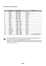
Page 18: ...x 720 60 Hz 11 WXGA 1280 x 800 60 Hz 12 WXGA 1440 x 900 60 Hz 13 WSXGA 1680 x 1050 60 Hz 14 UXGA 1920 x 1080 60 Hz 15 UXGA 1920 x 1080 75 Hz For DP HDMI only Note The DisplayPort of this monitor is pu...

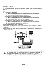
Page 19: ...nect DP Cable Only DP input model Optional a Make sure both the monitor and computer are powered OFF b Connect the DP cable to the computer 2 Connect the Audio Cable Optional 3 Insert the monitor powe...

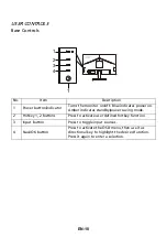
Page 20: ...wer on Amber indicates standby power saving mode 2 Hotkey 1 2 buttons Press to activate user defined hotkey function 3 Input button Press to toggle input sources 4 Navi OK button Press to activate the...

Page 21: ...g page Main Page The default function for buttons 2 and 3 are Brightness and Input You can use the Hot Key Assignment function to set these buttons to your preferred functions Adjusting the Modes From...

Page 22: ...ect the brightness setting using the Navi OK button When you are done press the Navi OK button to exit Selecting the Input Open the Input control and select the desired input You can also toggle Auto...

Page 23: ...lso press from any function page to select your preferred Mode Adjusting the Picture 1 Press the MENU button to open the OSD 2 Using the Navi OK button select Picture from the OSD Then navigate to the...

Page 24: ...simulate high resolution images by boosting the pixel density of the original source It can make images sharper and clear 10 H Position only Analog input model Adjust the horizontal position from 0 to...

Page 25: ...ou to adjust the luminance tone The default value is 2 2 standard value for Windows 5 Color temperature Default is warm You can choose Cool Warm Normal Bluelight or User 6 Modes Select your preferred...

Page 26: ...an saturation Adjusting the Audio 1 Press the MENU button to open the OSD 2 Using the Navi OK button select Audio from the OSD Then navigate to the setting you wish to change 3 Use the Navi OK button...

Page 27: ...rom the OSD Then navigate to the setting you wish to change 3 Use the Navi OK button to select the setting 4 Over Drive Select Off Normal or Extreme 5 Adaptive Sync Select On or Off Adaptive Sync is a...

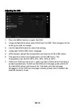
Page 28: ...timeout Adjust the delay before turning the off the OSD menu 6 Transparency Select the transparency of the OSD menu The transparency can be 0 OFF 20 40 60 or 80 7 OSD Lock OSD Lock function is used to...

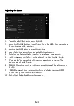
Page 29: ...put source 5 Auto Source Automatically searches for available input sources 6 Hot Key Assignment Select the function of Hot Key 1 or Hot Key 2 7 Wide Mode You can select which screen aspect you are us...

Page 30: ...EN 20 Product information 1 From any function page press to open Information page 2 Reset All Settings Reset all settings to the factory defaults...

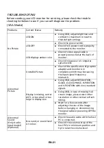
Page 31: ...the specification of graphics adapter and monitor is in compliance which may be causing the input signal frequency mismatch Display is missing center shift or too small or too large in display size Us...

Page 32: ...s properly connected to the monitor LED displays amber color Check if video signal cable is properly connected at the back of monitor Check if the power of computer system is ON Abnormal Sound Only Au...

Page 33: ...EN 23...

Page 34: ...not cause harmful interference and 2 this device must accept any interference received including interference that may cause undesired operation The following local Manufacturer Importer is responsib...

Page 35: ...Agency Acer is committed to offer products and services worldwide that help customers save money conserve energy and improve the quality of our environment The more energy we can save through energy...

Reviews: