Hardware Specifications and Configurations
1-19
Touchpad Basics
0
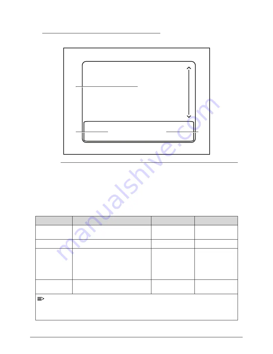
Figure 1-8. Touchpad
Move your finger across the Touchpad (1) to move the cursor.
Press the left (2) and right (3) buttons located beneath the Touchpad to perform
selection and execution functions. These two buttons are the equivalent of the
left and right buttons on a mouse. Tapping on the Touchpad is the same as
clicking the left button.
Function
Main Touchpad (1)
Left Button (2)
Right Button (3)
Execute
Tap twice (at the same speed as
double-clicking a mouse button).
Quickly click
twice.
Select
Tap once.
Click once.
Drag
Tap twice (at the same speed as
double-clicking a mouse button);
rest your finger on the Touchpad
on the second tap and drag the
cursor.
Click and hold,
then use finger
on the Touchpad
to drag the
cursor.
Access context
menu
Click once.
NOTE:
When using the Touchpad, keep it - and fingers - dry and clean. The Touchpad is
sensitive to finger movement; hence, the lighter the touch, the better the response.
Tapping too hard will not increase the Touchpad’s responsiveness.
1
2
3
Summary of Contents for TravelMate P243 SERIES
Page 1: ...TravelMate P243 Series SERVICEGUIDE ...
Page 11: ...CHAPTER 1 Hardware Specifications ...
Page 14: ...1 4 ...
Page 67: ...CHAPTER 2 System Utilities ...
Page 96: ...2 30 System Utilities ...
Page 97: ...CHAPTER 3 Machine Maintenance Procedures ...
Page 100: ...3 4 ...
Page 108: ...3 12 Machine Maintenance Procedures ID Size Quantity Screw Type A M2 5 6 0 1 C M2 0 3 0 2 ...
Page 120: ...3 24 Machine Maintenance Procedures ID Size Quantity Screw Type C M2 5 4 1 ...
Page 123: ...Machine Maintenance Procedures 3 27 ID Size Quantity Screw Type C M2 5 4 2 ...
Page 125: ...Machine Maintenance Procedures 3 29 ID Size Quantity Screw Type B M2 2 4 ...
Page 147: ...Machine Maintenance Procedures 3 51 ID Size Quantity Screw Type A M2 5 4 6 ...
Page 163: ...Machine Maintenance Procedures 3 67 ID Size Quantity Screw Type C M2 5 4 1 ...
Page 174: ...3 78 Machine Maintenance Procedures ID Size Quantity Screw Type A M2 5 6 0 1 C M2 0 3 0 2 ...
Page 177: ...CHAPTER 4 Troubleshooting ...
Page 201: ...CHAPTER 5 Jumper and Connector Locations ...
Page 208: ...5 8 Jumper and Connector Locations ...
Page 209: ...CHAPTER 6 FRU Field Replaceable Unit List ...
Page 210: ...6 2 Exploded Diagrams 6 4 FRU List 6 8 Screw List 6 18 ...
Page 227: ...CHAPTER 7 Model Definition and Configuration ...
Page 228: ...7 2 TravelMate P243 Series 7 3 ...
Page 256: ...7 30 Model Definition and Configuration ...
Page 257: ...CHAPTER 8 Test Compatible Components ...
Page 258: ...8 2 Microsoft Windows 7 Environment Test 8 4 ...
Page 269: ...CHAPTER 9 Online Support Information ...
Page 270: ...9 2 Introduction 9 3 ...


