Acer TravelMate 5760 Service Manual Download Page 110

3-18

Machine Maintenance Procedures

Keyboard Installation

0

1.

Flip keyboard frame over and install keyboard FPC (B) to mainboard connector (A). 
(

Figure 3-14)

2.

Locate keyboard frame flanges (A). (Figure 3-15)

Figure 3-15.

Keyboard Frame Flanges

3.

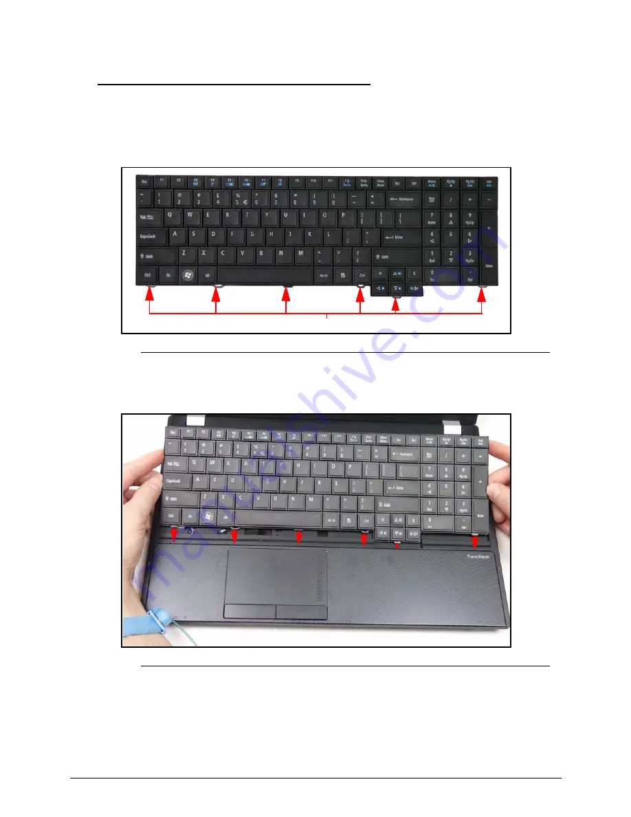
Insert keyboard frame flanges into upper cover slots. (Figure 3-16)

Figure 3-16.

Inserting Keyboard

4.

Place keyboard frame flush against the upper cover. (

Figure 3-12

)

5.

Secure the six latches

(

Figure 3-12

)

6.

Install battery pack.

A

A

Summary of Contents for TravelMate 5760

Page 1: ...TravelMate 5760 5760G SERVICE GUIDE ...

Page 2: ...cal magnetic optical chemical manual or otherwise without the prior written permission of Acer Incorporated Disclaimer The information in this guide is subject to change without notice There are no representations or warranties either expressed or implied with respect to the contents hereof and specifically disclaims any warranties of merchantability or fitness for any particular purpose The softw...

Page 3: ...ocument Book titles directory names file names path names and program process names are shown in italics Example the DRS5 User s Guide usr local bin fd the TPH15spool_M program Computer output text that represents information displayed on a computer screen such as menus prompts responses to input and error messages are shown in constant width Example 01 The server has been stopped User input text ...

Page 4: ...eneric service guide In such cases contact your regional offices or the responsible personnel channel to provide further technical details When ordering FRU parts Check the most up to date information available on your regional Web or channel If for whatever reason a part number change is made it may not be noted in this printed service guide Acer authorized Service Providers Your Acer office may ...

Page 5: ...ons and Accessories 1 10 Quality and Reliability Tests 1 10 Warranty 1 10 Software 1 11 Notebook Tour 1 12 Top View 1 12 Closed Front View 1 14 Left View 1 16 Right View 1 18 Base View 1 19 Touchpad Basics 1 20 Using the Keyboard 1 21 Windows Keys 1 22 Hotkeys 1 23 System Block Diagram 1 25 Specification Tables 1 26 Computer specifications 1 26 System Board Major Chips 1 27 Processor 1 27 Processo...

Page 6: ... Amplifier 1 41 Audio Interface 1 43 Wireless Module 802 11b g n 1 43 Battery 1 43 VRAM 1 43 USB Port 1 44 HDMI Port 1 44 AC Adapter 1 44 System Power Management 1 45 Card Reader 1 46 System LED Indicator 1 47 System DMA Specification 1 47 System Interrupt Specification 1 48 System IO Address Map 1 49 System I O Address Specifications Not available for this model 1 51 CHAPTER 2 System Utilities BI...

Page 7: ...wer Logic Door Installation 3 11 ODD Module Removal 3 12 ODD Module Installation 3 12 HDD Hard Disk Drive Module Removal 3 13 HDD Module Installation 3 14 HDD Carrier Removal 3 14 HDD Carrier Installation 3 14 Keyboard Removal 3 16 Keyboard Installation 3 18 Lower Cover Removal 3 19 Lower Cover Installation 3 21 WLAN Wireless Local Area Network Module Removal 3 22 WLAN Module Installation 3 23 PCH...

Page 8: ... 51 LCD Bezel Installation 3 52 CCD Charge Coupled Device Module Removal 3 53 CCD Module Installation 3 54 LCD Panel Removal 3 55 LCD Panel Installation 3 56 LCD Brackets Removal 3 57 LCD Brackets Installation 3 57 WLAN Antenna Removal 3 58 WLAN Antenna Installation 3 58 CHAPTER 4 Troubleshooting Introduction 4 3 General Information 4 3 Power On Issues 4 4 No Display Issues 4 5 LCD Failure 4 7 Key...

Page 9: ...Recovery by Crisis Disk 5 8 CHAPTER 6 FRU Field Replaceable Unit List Main Assembly 6 4 LCD Assembly 6 6 CHAPTER 7 Model Definition and Configuration TravelMate 5760 7 3 TravelMate 5760G 7 6 CHAPTER 8 Test Compatible Components TravelMate 5760 5760G 8 4 CHAPTER 9 Online Support Information Introduction 9 3 ...

Page 10: ...x ...

Page 11: ...CHAPTER 1 Hardware Specifications ...

Page 12: ...ability Tests 1 10 Warranty 1 10 Software 1 11 Notebook Tour 1 12 Top View 1 12 Closed Front View 1 14 Left View 1 16 Right View 1 18 Base View 1 19 Touchpad Basics 1 20 Using the Keyboard 1 21 Windows Keys 1 22 Hotkeys 1 23 System Block Diagram 1 25 Specification Tables 1 26 Computer specifications 1 26 System Board Major Chips 1 27 Processor 1 27 Processor Specifications 1 28 CPU Fan True Value ...

Page 13: ...Bluetooth Module 1 39 Camera 1 39 Mini Card 1 40 3G Card 1 40 Audio Codec and Amplifier 1 41 Audio Interface 1 43 Wireless Module 802 11b g n 1 43 Battery 1 43 VRAM 1 43 USB Port 1 44 HDMI Port 1 44 AC Adapter 1 44 System Power Management 1 45 Card Reader 1 46 System LED Indicator 1 47 System DMA Specification 1 47 System Interrupt Specification 1 48 System IO Address Map 1 49 System I O Address S...

Page 14: ...1 4 ...

Page 15: ... 35 W supporting Intel 64 architecture Intel Smart Cache Intel Core i3 2310M processor 3 MB L3 cache 2 10 GHz DDR3 1333 MHz 35 W supporting Intel 64 architecture Intel Smart Cache Mobile Intel HM65 Express Chipset Memory 0 Dual channel DDR3 SDRAM support Up to 4 GB of DDR3 system memory upgradable to 8 GB using two soDIMM modules for 64 bit OS Up to 2 GB of DDR3 system memory upgradable to 4 GB us...

Page 16: ...to 3765 2741 MB of TurboCache 2048 1024 MB of dedicated DDR3 VRAM up to 1717 MB of shared system memory supporting NVIDIA CUDA PhysX PureVideo HD technology OpenEXR High Dynamic Range HDR technology Shader Model 4 0 Microsoft DirectX 11 NVIDIA GeForce GT 520M with NVIDIA Optimus technology up to 2229 MB of TurboCache 512 MB of dedicated DDR3 VRAM up to 1717 MB of shared system memory supporting NV...

Page 17: ...d Networking 0 WLAN Intel Centrino Advanced N 6205 802 11a b g n Wi Fi CERTIFIED with Acer Nplify featuring MIMO technology Acer InviLink Nplify 802 11b g n Wi Fi CERTIFIED Acer InviLink Nplify 802 11b g Wi Fi CERTIFIED Supporting Acer SignalUp wireless technology WPAN Bluetooth 3 0 HS Bluetooth 2 1 EDR WWAN UMTS HSPA at 850 900 1900 2100 MHz and quad band GSM GPRS EDGE at 850 900 1800 1900 MHz up...

Page 18: ...oot Authentication Module File Encryption Decryption and Personal Secure Drive under Acer ProShield Data Protection Module File Shredder under Acer ProShield Data Removal Module BIOS user supervisor HDD passwords Kensington lock slot Power Adapter and Battery 0 ACPI 3 0 CPU power management standard supports Standby and Hibernation power saving modes ENERGY STAR Battery 99 Wh 9000 mAh 9 cell Li io...

Page 19: ...edia control keys printed on keyboard play pause stop previous next volume up volume down Control keys Acer programmable key Acer Backup key Acer Bio Protection fingerprint reader1 Volume mute key RF Switch Input and Output 0 Multi in 1 card reader SD MMC MS MS PRO xD Three USB 2 0 ports HDMI port with HDCP support External display VGA port Headphone speaker jack Microphone in jack Ethernet RJ 45 ...

Page 20: ...DIMM module 6 cell Li ion battery pack 9 cell Li ion battery pack TravelMate 5760 0 3 pin 65 W AC adapter TravelMate 5760G 0 3 pin 90 W AC adapter Quality and Reliability Tests 0 Temperature and humidity Hinge life Weight and pressure Acoustics Spillage Free drop Shock and vibration Electrostatic discharge immunity Keyboard switch life MTBF mean time between failures Warranty 0 One year Internatio...

Page 21: ... Security Acer ProShield Absolute Data Protect EMEA PA only McAfee Internet Security Suite Trial Multimedia Corel WinDVD NTI Media Maker Communication and ISP Acer Crystal Eye Acer Video Conference Manager Microsoft Silverlight Skype Windows Live Essentials 2011 Web links and utilities Acer Accessory Store Belgium France Germany Italy Netherlands Spain Sweden UK only Acer Identity Card Acer Regist...

Page 22: ...Figure 1 1 Top View Table 1 1 Top View No Icon Item Description 1 Integrated webcam Web camera for video communication only for certain models 2 Display screen Also called Liquid Crystal Display LCD displays computer output Configuration may vary by model 1 2 3 4 5 6 7 8 9 10 ...

Page 23: ... when Num Lock is activated Caps Lock indicator Lights up when Caps Lock is activated 6 Keyboard For entering data into your computer 7 Microphone Internal microphone for sound recording 8 Touchpad Touch sensitive pointing device which functions like a computer mouse 9 Acer Bio Protection Fingerprint reader Fingerprint reader for biometric data protection 10 Click buttons left and right The left a...

Page 24: ...s Charging The light shows amber when the battery is charging Fully charged The light shows blue when in AC mode HDD indicator Indicates when the hard disk drive is active 2 Multi in 1 card reader Accepts Secure Digital SD MultiMediaCard MMC Memory Stick PRO MS PRO xD Picture Card xD NOTE Push to remove install the card Only one card can operate at any given time 3 Communication switch Enables dis...

Page 25: ...ations 1 15 4 Communication indicator Indicates the status of the computer s communication devices NOTE The front panel indicators are visible even when the computer cover is closed Table 1 2 Front View Continued No Icon Item Description ...

Page 26: ...ble object such as a table or handle of a locked drawer Insert the lock into the notch and turn the key to secure the lock Some keyless models are also available 2 Ethernet RJ 45 port Connects to an Ethernet 10 100 1000 based network 3 External display VGA port Connects to a display device e g external monitor LCD projector 4 HDMI port Supports high definition digital video connections 5 USB 2 0 p...

Page 27: ...Accepts inputs from external microphones Headphones speaker jack Connects to audio devices e g speakers headphones NOTE Supports compatible 3 5 mm headsets with built in microphone e g Acer smart handheld headsets Table 1 3 Left View Continued No Icon Item Description ...

Page 28: ...optical drive accepts CDs or DVDs 3 Optical drive access indicator Lights up when the optical drive is active 4 Optical drive eject button Ejects the optical disc from the drive 5 Emergency eject hole Ejects the optical drive tray when the computer is turned off NOTE Insert a paper clip to the emergency eject hole to eject the optical drive tray when the computer is off 6 DC in jack Connects to an...

Page 29: ... View Table 1 5 Base View No Icon Item Description 1 Battery lock Locks the battery in position 2 Hard disk bay Houses the computer s hard disk secured with screws 3 Battery release latch Releases the battery for removal 4 Battery bay Houses the computer s battery pack 1 2 4 3 ...

Page 30: ...n TouchPad 1 Right Button 2 Left Button 3 Execute Tap twice at the same speed as double clicking a mouse button Quickly click twice Select Tap once Click once Drag Tap twice at the same speed as double clicking a mouse button rest your finger on the TouchPad on the second tap and drag the cursor Click and hold then use finger on the Touchpad to drag the cursor Access context menu Click once NOTE W...

Page 31: ... is on the embedded keypad is in numeric mode The keys function as a calculator complete with the arithmetic operators and Use this mode when doing a lot of numeric data entry A better solution would be to connect an external keypad Scroll Lock Fn F12 When Scroll Lock is on the screen moves one line up or down when the up or down arrow keys are pressed respectively Scroll Lock does not work with s...

Page 32: ... all windows F1 Show the help window E Open Windows Explorer F Search for a file or folder D Show the desktop Ctrl F Search for computers if you are on a network L Lock your computer if you are connected to a network domain or switch users if you re not connected to a network domain Ctrl Tab Moves focus from Start menu to the Quick Launch toolbar to the system tray use or to move focus to items on...

Page 33: ...oard Hotkeys Hotkey Icon Function Description Fn F3 Communication switch Enables disables the computer s communication devices Communication devices may vary by configuration Fn F4 Sleep Puts the computer in Sleep mode Fn F5 Display toggle Switches display output between the display screen external monitor if connected and both Fn F6 Screen blank Turns the display screen backlight off to save powe...

Page 34: ...Fn Volume up Increases audio volume Fn Volume down Decreases audio volume Fn Home Play Pause Plays or pauses media files Fn Pg Up Stop Stops media file Fn Pg Dn Previous Plays the previous media file in the play sequence Fn End Next Plays the next media file in the play sequence Table 1 10 Keyboard Hotkeys Continued Hotkey Icon Function Description ...

Page 35: ...Hardware Specifications and Configurations 1 25 System Block Diagram 0 Figure 1 9 System Block Diagram ...

Page 36: ...disc 0 C 35 C 32 F 95 F Operating writing to optical disc 5 C 35 C 41 F 95 F Nonoperating 20 C 65 C 4 F 140 F Relative humidity Operating 20 to 80 Nonoperating 20 to 80 Maximum altitude unpressurized Operating 15 to 3 048m 50 to 10 000ft Nonoperating 15 to 12 192m 50 to 40 000ft Shock Operating 105G 2 ms half sine Nonoperating 220 G 2 ms half sine Random vibration Operating 0 6G 5 500HZ 30min per ...

Page 37: ... Foxconn Bluetooth ATH BU12 Wireless Heros HB97 PCMCIA N A Audio codec Conexant CX20584 21Z Card reader Realtek RTS5209 Item Specification CPU type Intel Sandy Bridge Dual Core processor CPU package rPGA988B Core Logic Four or two execution cores A 32 KB instruction and 32 KB data first level cache L1 for each core A 256 KB shared instruction data second level cache L2 for each core Up to 8 MB sha...

Page 38: ...nm 4MB rPGA988B 35W CPU Temperature Fan Speed RPM SPL Spec dBA Fan On 35 C Fan Off 30 C 2600 28 Fan On 43 C Fan Off 39 C 3150 31 Fan On 53 C Fan Off 48 C 3450 34 Fan On 63 C Fan Off 58 C 3800 37 Fan On 75 C Fan Off 69 C 4050 40 Fan On 80 C Fan Off 77 C 5V N A Throttling 50 On 82 C OFF 77 C OS shut down at 85 C H W shut down at 85 C CPU Temp Fan Speed RPM SPL Spec dBA Fan On 35 C Fan Off 30 C 2600 ...

Page 39: ...rottling 50 On 97 C OFF 93 C OS shut down at 100 C H W shut down at 100 C Item Specification Memory controller Built in at CPU Memory size DDRIII 1333 1GB 2GB 4GB DIMM socket number 2 Supports memory size per socket 8GB Supports maximum memory size Total 16GB Supports DIMM type SODIMM Supports DIMM Speed DDRIII Support DIMM voltage 1 5V Supports DIMM package 20 4 pins DDR3 SODIMM Slot 1 MB Slot 2 ...

Page 40: ...nations continued 2048 1024 3072 2048 2048 4096 2048 4096 6144 2048 8192 10240 4096 0 4096 4096 1024 5120 4096 2048 6144 4096 4096 8192 4096 8192 12288 8192 0 8192 8192 1024 9216 8192 2048 1024 8192 4096 12288 8192 8192 16384 Slot 1 MB Slot 2 MB Total Memory MB ...

Page 41: ...mpliance embed in Direct X 11 and Shader Model 5 0 OpenGL 3 2 NVIDA Ageia PhysXTM technology NVIDA CUDA technology LVDS Engine and Memory DP Spread Spectrum Support The following video formats are supported MPEG 2 MPEG 4 Part 2 Advanced Simple Profile H 264 SVC codec support VC1 DivX version 3 11 and later MVC Sampling rate 60Hz Item Specification BIOS vendor Insyde BIOS Version 1 04 BIOS ROM type...

Page 42: ...ecification Vendor Model Name Hitachi HTS545025B9A 300 WD WD2500BPVT 22ZEST0 Hitachi HTS545032B9A 300 WD WD3200BPVT 22ZEST0 Hitachi HTS545050B9A 300 WD WD5000BPVT 22HXZT1 TOSHIBA MK6459GSXP WD WD6400BPVT 22HXZT1 Capacity GB 250 320 500 640 Bytes per sector 512 512 512 512 Data heads 2 2 4 3 4 4 Drive Format Disks 1 1 2 2 Spindle speed RPM 5400 Performance Specifications Buffer size 8MB Interface S...

Page 43: ...GSXP Capacity GB 750 Bytes per sector 512 512 Data heads 4 4 Drive Format Disks 2 2 Spindle speed RPM 5400 Performance Specifications Buffer size 8M Interface SATA Fast data transfer rate Mbits sec max 3 0 Media data transfer rate Mbytes sec max 97 584 3 1195 5 Mbits s DC Power Requirements Voltage tolerance 5V 5 Item Specification ...

Page 44: ... 9G DVD R Book 2 0 4 7G General Authoring DVD R Version 1 0 DVD RW DVD RW Non CPRM CPRM DVD R Dual DVD RAM CD CD DA Red Book Standard Audio CD CD TEXT CD ROM Yellow Book Mode1 2 Standard Data CD ROM XA Mode2 Form1 2 Photo CD Multi Session CD I Green Book Mode2 Form1 2 Ready Bridge CD Extra CD Plus Blue Book Audio Text Video Video CD White Book MPEG1 CD R Orange Book Part U CD RW HSRW Orange Book P...

Page 45: ...le disc format KODAK PhotoCD Single and Multi session CD Extra CDPLUS Video CD CD text data Read Write CD R discs Read Write CD RW discs Read Write DVD ROM DVD R Ver 2 0 2 1 for General Read Write DVD R DL Ver 3 0 Read Write DVD RW Ver 1 0 1 1 1 2 Read Write DVD R Ver 1 3 Read Write DVD R DL Ver1 0 1 1 Read Write DVD RW Ver 1 3 Read Write DVD RW high speed Ver 1 0 Read Write DVD RAM Ver 2 0 2 1 2 ...

Page 46: ...4 Display resolution pixels 1366 H x768 V Pixel Pitch mm 0 2588X0 2588 Typical White Luminance cd m2 also called Brightness 200 typ 5 points average 170 min 5 points average Contrast Ratio 400 typ Response Time Optical Rise Time Fall Time msec 8 typ 16 Max Typical Power Consumption watt 5 6 max Include Logic and Blu power Weight without inverter 450 max Physical Size mm 359 3 x 209 5 typical 360 x...

Page 47: ...Ratio 500 typ Response Time Optical Rise Time Fall Time msec 16 Max Typical Power Consumption watt 4 5 max Include Logic and Blu power Weight without inverter 450 max Physical Size mm 359 3 x 209 5 typical 360 x 210 x 5 5 max Electrical Interface 1 channel LVDS Viewing Angle degree Horizontal Right CR 10 Left Vertical Upper CR 10 Lower 45 45 15 35 typical 40 40 10 30 min Item Specification Vendor ...

Page 48: ...768 60Hz 16 9 Y Y Y Y Y Item Specification VGA Chip Nvidia N12P GS or N12P GV Supports Advanced Scheduler 2 0 1 0 XPDM support DX10 1 DX10 DX9 support OGL 3 0 support Support CRT LVDS HDMI DP interface concurrent Dual channel LVDS interface support single channel 24 bpp dual link Direct X 11 and Shader Model 5 0 OpenGL 3 2 support Resolution 16 bits 32 bits 36 bits 48 bits 800x600p 60Hz 16 9 Y Y Y...

Page 49: ...pliant Point to multipoint operation External USB interface for data Onboard antenna and SMA RF connector Coexistence support Item Specifications Controller Foxconn Bluetooth ATH BU12 Features Single chip Bluetooth v2 1 3 0 EDR integrated solution USB 2 0 full speed device interface with support for Device Firmware Upgrade DFU SPI interface supports external serial flash devices Two on chip 1 2V l...

Page 50: ...M GPRS EDGE 850 900 1800 1900 MHz UMTS equalizer and receive diversity HSDPA packet data service of up to 7 2 Mbit s HSUPA data service of up to 5 76 Mbit s UMTS PS domain data service of up to 384 Kbit s EDGE packet data service of up to 236 8 Kbit s GPRS packet data service of up to 85 6 Kbit s Circuit Switched CS domain data service based on UMTS and GSM SMS based on CS Packet Switched PS domai...

Page 51: ...MIC boost supporting 2 digital microphone elements Works with all digital microphones Internal microphone boost Digital 0 12 24 36 48 dB Analog 0 10 20 30 40 dB Microphone Security Control Please contact Conexant Sales FAE for additional confidential document to disable the bit in microphone from the BIOS Exceeds Windows Vista and Windows 7 Desktop and Notebook Premium Logo Requirements WLP4 0 D F...

Page 52: ... jacks using only two sense pins Dual Sony Philips Digital Interface S PDIF outputs Digital Mixer Simultaneous DAC and SPDIF engines 3 3 V analog and I O operation uses Vaux for power management modes SmartAudio GUI optional advanced audio control Digital Parametric SmartEQ with Dynamic Range Compression DRC Enhances the sound quality on low cost speakers Night Mode 3D Expander Third party Logo so...

Page 53: ... Yes Internal speaker quantity Yes 2W speakers x2 Item Specification Chipset Atheros HB97 Data throughput 11 54 Mbps up to 300 Mbps for Draft N Protocol b g n Interface PCI E Item Specification Vendor Model name SANYO AS10D31 SANYO AS10D31 PANASONIC AS10D51 SIMPLO AS10D73 SIMPLO AS10D75 SANYO AS10D3E PANASONICAS10D5E SANYO AS10G3E Battery Type Li Ion Li Ion Li Ion Pack capacity 4400mAh 6000mAh 900...

Page 54: ... 16 7 million colors Number of HDMI port s 1 Location 1 left side Item Specification Input rating 100 240V 1 7A 1 7A 50 60Hz Maximum input AC current 1 7A 1 7A 50 60Hz Maximum input AC current 264 Vrms Inrush current 264 Vac Cold Hot start No damage meet fuse and bridge diode I2t de rating Efficiency Meets EPA 2 0 level V requirement The adapter efficiency shall be more than 87 that is the average...

Page 55: ... in the system are turned off completely Working G0 S0 Individual devices such as the CPU and hard disc may be power managed in this state Suspend to RAM S3 CPU set power down VGA Suspend Audio Power Down Hard Disk Power Down CD ROM Power Down Super I O Low Power mode Save to Disk S4 Also called Hibernation Mode System saves all system states and data onto the disc prior to power off the whole sys...

Page 56: ...ion 1 00 00 Compliant with Memory Stick XC HG Duo Format Specification Version 1 00 00 Compliant with Memory Stick XC Micro Format Specification Version 1 00 00 Compliant with Memory Stick XC HG Micro Format Specification Version 1 00 00 Compliant with Memory Stick PRO HG Duo Format Specification Version 1 03 00 Compliant with Memory Stick HG Micro Format Specification Version 1 00 00 Compliant wi...

Page 57: ...HDD access state HDD access active Blue Wireless state Wifi on Amber Power button backlight Blue color solid on System on Blue color off System off Battery state Full charging Blue Battery charging Amber Legacy Mode Power Management DMA0 Not applicable DMA1 Not applicable DMA2 Not applicable DMA3 Not applicable DMA4 Direct memory access controller DMA5 Not applicable DMA6 Not applicable DMA7 Not a...

Page 58: ... IRQ1 Standard PS 2 Keyboard IRQ2 Not in use IRQ3 Not in use IRQ4 Direct memory access controller IRQ5 Not in use IRQ6 Not in use IRQ7 Not in use IRQ8 System CMOS real time clock IRQ9 Not in use IRQ10 Not in use IRQ11 Not in use IRQ12 Synaptics PS 2 Port Touchpad IRQ13 Numeric data processor IRQ14 Not in use IRQ15 Not in use ...

Page 59: ...ler 040 043 System timer 04E 04F Motherboard resources 050 053 System timer 60 Standard PS 2 Keyboard 61 Motherboard resources 62 Microsoft ACPI Compliant Embedded Controller 63 Motherboard resources 64 Standard PS 2 Keyboard 65 Motherboard resources 66 Microsoft ACPI Compliant Embedded Controller 67 Motherboard resources 070 077 System CMOS real time clock 80 Motherboard resources 081 091 Direct ...

Page 60: ...164E 164F Motherboard resources 2000 2FFF Inte 6 Series C200 Series Chipset Family PCI Express Root Port 6 1C1A 3000 3FFF Intel 6 Series C200 Series Chipset Family PCI Express Root Port 5 1C18 4000 4FFF Intel 6 Series C200 Series Chipset Family PCI Express Root Port 2 1C12 5000 5FFF 2nd generation Intel Core processor family PCI Express Controller 0101 6000 603F Intel HD Graphics Family 6060 607F ...

Page 61: ... for this model I O address hex System Function shipping configuration 220 22F 230 26D 26E 26 278 27F 280 2AB 2A0 2A7 2A8 2E7 2E8 2EF 2F0 2F7 2F8 2FF 300 31F 320 36F 370 377 378 37F 380 387 388 38B 38C 3AF 3B0 3BB 3BC 3BF 3C0 3DF 3E0 3E1 3E2 3E3 3E8 3EF 3F0 3F7 3F8 3FF CF8 CFB PCIDIVO 1 PCIDIVO 1 ...

Page 62: ...1 52 Hardware Specifications and Configurations ...

Page 63: ...CHAPTER 2 System Utilities ...

Page 64: ...Main 2 6 Security 2 8 Boot 2 13 Exit 2 14 BIOS Flash Utilities 2 15 DOS Flash Utility 2 16 WinFlash Utility 2 18 HDD BIOS Password Utilities 2 20 Clearing HDD Passwords 2 20 Clearing BIOS Passwords 2 22 Miscellaneous Tools 2 24 Using DMI Tools 2 24 Using the LAN MAC EEPROM Utility 2 29 ...

Page 65: ...he parameter to Enabled To change the boot device without entering the BIOS SETUP press F12 during POST to enter the multi boot menu Navigating the BIOS Utility 0 Six menu options are Information Main Security Boot Exit To navigate through the following Menu use the left and right arrow keys Item use the up and down arrow keys Change parameter value press F5 or F6 Exit Press Esc Load default setti...

Page 66: ...Core TM 2 Duo CPU T7300 CPU Speed 2 00GHz HDD Model Name ST960821A PM HDD Serial Number 3LF005DB ATAPI Model Name MATSHITADVD System BIOS Version V1 00 VGA BIOS Version ATI V008 050I 0 26 00 Serial Number xxxxxxxxxxxxxxxxxxxx Max 22 Byte Asset Tag Number xxxxxxxxxxxxxxxxxxxx Max 32 Byte Product Name xxxxxxxxxxxxxxxx Max 16 Byte Manufacturer Name xxxxxxxxxxxxxxxxxxxx Max 16 Byte UUID xxxxxxxxxxxxxx...

Page 67: ...E master ATAPI Model Name Model name of Optical device installed in system System BIOS Version System BIOS version VGA BIOS Version VGA video graphics array firmware version of system Serial Number Serial number of unit Asset Tag Number Asset tag number of system Product Name Product name of the system UUID Universally Unique Identifier Table 2 1 BIOS Information Continued Parameter Description ...

Page 68: ... Boot Enabled Network Boot Enabled F12 Boot Menu Disabled D2D Recovery Enabled SATA Mode AHCI Mode F1 Help Select Item F5 F6 Change Values F9 Setup Default ESC Exit Select Menu Enter Select SubMenu F10 Save and Exit Table 2 2 BIOS Main Parameter Description Format Option System Time BIOS system time in 24 hour format Format HH MM SS hour minute second System Date BIOS system date Format MM DD YYYY...

Page 69: ...ed or Disabled F12 Boot Menu Option to use boot menu during POST Option Enabled or Disabled D2D Recovery Option to use D2D Recovery function Option Enabled or Disabled SATA Mode Option to set SATA controller mode Option AHCI or IDE Table 2 2 BIOS Main Continued Parameter Description Format Option ...

Page 70: ...User Password Is Clear HDD Password Is Clear Set Supervisor Password Enter Set User Password Enter Set HDD Password Enter Power on Password Disabled F1 Help Select Item F5 F6 Change Values F9 Setup Default ESC Exit Select Menu Enter Select SubMenu F10 Save and Exit Table 2 3 BIOS Security Parameter Description Option Supervisor Password Is Supervisor password setting Clear or Set User Password Is ...

Page 71: ...gure 2 4 NOTE NOTE To change an existing password refer to Changing a Password Figure 2 4 Setting a Password Set Supervisor Password 2 Type a new password in the Enter New Password field and press Enter NOTE NOTE The following characters may be used in a password Password on Boot CAUTION If Power on Password authentication is enabled the BIOS password can only be cleared by initiating the Crisis D...

Page 72: ...Supervisor Password parameter is shown as Set c Press F10 to save changes and exit BIOS Setup Utility 5 If new password and confirm new password strings do not match the Setup Warning dialog is shown Figure 2 6 Figure 2 6 Setting a Password Passwords Do Not Match a Press Enter to return to the BIOS Setup Utility Security menu b The Supervisor Password parameter is shown as Clear c To try to set a ...

Page 73: ...upervisor Password and press Enter The Set Supervisor Password dialog is shown Figure 2 8 Figure 2 8 Changing a Password Set Supervisor Password 2 Type current password in Enter Current Password field and press Enter 3 Type new password in Enter New Password field and press Enter 4 Retype new password in Confirm New Password field and press Enter 5 If new password and confirm new password strings ...

Page 74: ...OS Setup Utility Security menu b The Supervisor Password parameter is shown as Clear c To try to change the password again repeat steps 1 through 4 7 If new password and confirm new password strings do not match the Setup Warning dialog is shown Figure 2 11 Figure 2 11 Changing a Password Passwords Do Not Match a Press Enter to return to the BIOS Setup Utility Security menu b The Supervisor Passwo...

Page 75: ...re 2 12 BIOS Boot InsydeH20 Setup Utility Rev 3 5 Information Main Security Boot Exit Item Specific Help Boot priority order USe or to select a device then press F5 to move it down the list or F6 to move it up the list Press Esc to escape the menu 1 HDD Hitachi HTS545032B9A300 2 ATAPI CDROM MATSHITADVD RAM UJ8A2AS 3 USB FDD 4 Network Boot Atheros Boot Agent 5 USB HDD 6 USB CDROM F1 Help Select Ite...

Page 76: ...ard Changes Load Setup Defaults Discard Changes Save Changes F1 Help Select Item F5 F6 Change Values F9 Setup Default ESC Exit Select Menu Enter Select SubMenu F10 Save and Exit Table 2 4 BIOS Exit Parameter Description Exit Saving Changes Exit BIOS utility and save setup item changes to system Exit Discarding Changes Exit BIOS utility without saving setup item changes to system Load Setup Default...

Page 77: ...ate one before BIOS Flash utility is used Refer to BIOS Recovery by Crisis Disk NOTE NOTE Do not install memory related drivers XMS EMS DPMI when BIOS Flash is used NOTE NOTE Use AC adaptor power supply when running BIOS Flash utility If battery pack does not contain power to finish loading BIOS Flash do not boot system Perform the following to run BIOS Flash 1 Prepare a bootable USB HDD 2 Copy Fl...

Page 78: ... 6 Execute ZRJ_101 to update BIOS Figure 2 15 Figure 2 15 Executing ZRJ_0 08 InsydeH20 Setup Utility Rev 3 5 Information Main Security Boot Exit Item Specific Help Boot priority order USe or to select a device then press F5 to move it down the list or F6 to move it up the list Press Esc to escape the menu 1 USB HDD USB 2 0 Flash Disk 2 IDE0 WDC WD 2500BPVT 22ZEST0 3 IDE1 4 USB FDD 5 Network Boot A...

Page 79: ...message Flash Programming Complete is shown System will restart automatically when finished NOTE NOTE If AC power is not connected the following message is shown Figure 2 17 Plug in the AC power to continue Figure 2 17 AC Power Warning X XXx XXXXXXXX XXXXXXXX XXXXXXXX XXXXXXXX ZRJ ZRJ 0 05 0 08 1 4c Warning No AC power connect ...

Page 80: ...o use the WinFlash Utility 1 Double click the WinFlash executable 2 Click OK to begin the update A progress screen is shown Figure 2 18 Figure 2 18 InsydeFlash NOTE NOTE If the error message appears Figure 2 19 check the system BIOS ROM file size ZRJ ZRJ V0 05 V0 08 ...

Page 81: ...System Utilities 2 19 Figure 2 19 InsydeFlash ...

Page 82: ...rd is incorrectly entered three times an error is generated Figure 2 20 Figure 2 20 Password Error Status To reset the HDD password perform the following 1 Press Enter to continue The Select Item dialog is shown Figure 2 21 Figure 2 21 Select Item 2 Use the and keys to highlight Enter Unlock Password and press Enter The Enter Unlock Password dialog is shown Figure 2 22 Figure 2 22 Enter Unlock Pas...

Page 83: ...e a password unlock code Use the format UnlockHD key code with the code noted in Figure 2 22 Example UnlockHD 54591747 The command generates a password which can be used for unlocking the HDD Password 41499389 Figure 2 23 Unlock Password 5 On original device enter password Figure 2 23 in Enter Unlock Password dialog Figure 2 24 Figure 2 24 Unlock Password Dialog Enter Unlock Password Key 54591747 ...

Page 84: ...mpt for the password at system POST or upon entering the BIOS setup menu There are two methods for clearing the BIOS password A hardware method and a software method Hardware Method 0 1 Remove AC adapter 2 Locate the XXXXXXXX point A Figure 2 25 Figure 2 25 CMOS Jumper Overview 3 Short each point Figure 2 26 Figure 2 26 CMOS Jumper ...

Page 85: ...wn repeat steps 1 through 5 Software Method 0 If wrong supervisor password is entered three times the System will halt dialog is shown Figure 2 27 Figure 2 27 Supervisor Password Error 1 At a DOS prompt enter ClearSuPw exe Figure 2 28 Figure 2 28 Clear Supervisor Password Utility 2 When message Clear the SU Pws completely is shown supervisor password has been removed Table 2 5 Item Description ...

Page 86: ... shows Verifying DMI pool data it is checking that the table correlates with the hardware before sending it to the operating system Windows etc To update the DMI Pool perform the following 1 Boot to DOS 2 At the prompt enter qdmi301 exe To execute a specific function select the associated menu number Figure 2 29 Figure 2 29 DMI Tools Main Menu Screen 3 Press 1 to modify asset tag key Figure 2 30 ...

Page 87: ...System Utilities 2 25 Figure 2 30 Asset Tag Menu Item 4 Press 2 to modify the product number key Figure 2 31 ...

Page 88: ...2 26 System Utilities Figure 2 31 Product Name Menu Item 5 Press 3 to modify serial number key Figure 2 32 Serial Number Menu Item 6 Press 4 to modify the 1394 GUID number key ...

Page 89: ...System Utilities 2 27 Figure 2 33 1394 GUID Number Menu Item 7 Press 0 to exit Figure 2 34 Exit Menu Item ...

Page 90: ...t the command prompt type VEEPROM to write any changes in the data to the EEPROM Figure 2 35 VEEPROM Command Prompt NOTE NOTE When using any of the write options restart the system to make the new DMI data effective C VEEPROM_ ...

Page 91: ...values to eeprom Figure 2 37 Figure 2 37 MAC BAT 3 Reboot computer when process has completed Table 2 6 Field Name Value Description Title MAC Address byte N A WriteData 001122334455 MAC value StartAddr 7A MAC address WriteLeng 6 MAC value length KeepByte 0 N A MAC CFG Notepad MAC CFG Notepad Title MAC Address byte WriteData 001122334455 StartAddr 7A WriteLeng 6 KeepByte 0 File Edit Format View He...

Page 92: ...2 30 System Utilities ...

Page 93: ...CHAPTER 3 Maintenance Procedures ...

Page 94: ... 21 WLAN Wireless Local Area Network Module Removal 3 22 WLAN Module Installation 3 23 PCH Heatsink Removal 3 24 PCH Heatsink Installation 3 24 RTC Battery Removal 3 25 RTC Battery Installation 3 25 DIMM Dual In line Memory Module Module Removal 3 26 DIMM Module Installation 3 26 Bluetooth Module Removal 3 27 Bluetooth Module Installation 3 28 USB Module Removal 3 29 USB Module Installation 3 29 T...

Page 95: ... Bezel Installation 3 52 CCD Charge Coupled Device Module Removal 3 53 CCD Module Installation 3 54 LCD Panel Removal 3 55 LCD Panel Installation 3 56 LCD Brackets Removal 3 57 LCD Brackets Installation 3 57 WLAN Antenna Removal 3 58 WLAN Antenna Installation 3 58 ...

Page 96: ...3 4 ...

Page 97: ...ay also differ from the actual model During the removal and installation of components make sure all available cable channels and clips are used and that the cables are installed in the same position All prerequisites must be performed prior to performing maintenance Recommended Equipment 0 The following tools are required to perform maintenance on the notebook Wrist grounding strap and conductive...

Page 98: ...ce Flowchart 0 The flowchart in Figure 3 1 provides a graphic representation of the module removal and installation sequences It provides information on what components need to be removed and installed during servicing Figure 3 1 Maintenance Flow ...

Page 99: ... and install sequence Observe the order of the sequence to avoid damage to any of the hardware components Perform the following prior to performing any maintenance procedures 1 Remove power A from the system and peripherals Figure 3 2 2 Remove all cables from system Figure 3 2 AC Adapter 3 Place system on a stable work surface A ...

Page 100: ...k position Figure 3 3 Figure 3 3 Battery 3 Move release switch B to release battery pack A 4 Remove battery pack NOTE NOTE Follow local regulations for battery disposal Battery Pack Installation 0 1 Move lock unlock latch C into unlock position Figure 3 3 2 Install battery A 3 Move battery lock unlock latch C into lock position A C B ...

Page 101: ... 3 9 Dummy Card Removal 0 1 Push in dummy card A to release it from spring latch Figure 3 4 2 Remove dummy card Figure 3 4 Dummy Card Dummy Card Installation 0 1 Insert dummy card A Figure 3 4 2 Push card until spring latch locks A ...

Page 102: ...t in battery bay A Figure 3 5 Figure 3 5 Lower Cover Overview with Base Door 2 Push in 3G card C to release it from spring latch Figure 3 6 Figure 3 6 3G Card 3 Remove 3G card 3G Card Installation 0 1 Insert 3G card A into card slot Figure 3 6 2 Push card until spring latch locks 3 Install battery pack A B C ...

Page 103: ... B on lower cover Refer to Figure 3 5 2 Loosen two 2 captive screws A Figure 3 7 Figure 3 7 Lower Cover Door Screws 3 Remove door from lower cover Lower Logic Door Installation 0 1 Install lower logic door on lower cover 2 Secure two 2 captive screws A on lower logic door to lower cover Figure 3 7 3 Install battery pack A ...

Page 104: ... ODD Module A on lower cover Figure 3 8 2 Remove screw B Figure 3 8 ODD Module 3 Remove ODD module from lower cover ODD Module Installation 0 1 Install ODD module in lower cover 2 Install and secure screw B on lower cover Figure 3 8 3 Install battery pack ID Size Quantity Screw Type B M2 5x5 0 1 B A ...

Page 105: ...isite Battery Pack Removal 1 Locate HDD module A on lower cover Figure 3 9 Figure 3 9 Lower Cover with HDD Module 2 Disconnect HDD module cable B from mainboard connector 3 Remove HDD module from lower cover by lifting plastic tab A Figure 3 10 Figure 3 10 HDD Module Removal A B A ...

Page 106: ...requisite HDD Hard Disk Drive Module Removal 1 Remove four 4 screws A from HDD brackets Figure 3 11 Figure 3 11 HDD Module Brackets 2 Remove HDD brackets B and C from HDD module 3 Remove HDD module cable D from HDD module connector HDD Carrier Installation 0 1 Install HDD module cable D to HDD module connector Figure 3 11 2 Install and secure brackets B and C to HDD module with four 4 screws A 3 I...

Page 107: ...Machine Maintenance Procedures 3 15 ID Size Quantity Screw Type A M2 0x3 0Ni 4 ...

Page 108: ...l 1 Locate and unlock six 6 latches above keys Esc F4 F8 F12 Del and End Figure 3 12 Figure 3 12 Keyboard NOTE NOTE Keyboard FPC Flexible Printed Circuit can be damaged if removed while mainboard connector is locked 2 Lift keyboard frame from upper cover starting from top edge Figure 3 13 ...

Page 109: ...Machine Maintenance Procedures 3 17 Figure 3 13 Lifting Keyboard 3 Carefully flip keyboard over Figure 3 14 Figure 3 14 Keyboard FPC 4 Remove keyboard FPC B from mainboard connector A B A ...

Page 110: ...onnector A Figure 3 14 2 Locate keyboard frame flanges A Figure 3 15 Figure 3 15 Keyboard Frame Flanges 3 Insert keyboard frame flanges into upper cover slots Figure 3 16 Figure 3 16 Inserting Keyboard 4 Place keyboard frame flush against the upper cover Figure 3 12 5 Secure the six latches Figure 3 12 6 Install battery pack A A ...

Page 111: ...venteen 17 screws A from lower cover Figure 3 17 Figure 3 17 Lower Cover 2 Remove five 5 screws B from battery bay NOTE NOTE Connectors on right side of mainboard USB HDMI are set in lower cover slots Do not use force when removing lower cover 3 Lift side A of lower cover just enough to allow lower cover to clear upper cover Figure 3 18 A B A ...

Page 112: ...3 20 Machine Maintenance Procedures Figure 3 18 Lifting Left Side of Lower Cover 4 Slide and remove lower cover from side B Figure 3 19 Figure 3 19 Removing Lower Cover A B ...

Page 113: ...f lower cover by sliding lower cover towards side A at slight angle Figure 3 19 3 Install left side A of lower cover Figure 3 18 4 Install and secure five 5 screws B in battery bay Figure 3 17 5 Install and secure seventeen 17 screws A on lower cover 6 Install HDD module 7 Install lower logic door ID Size Quantity Screw Type A M2 5x5 0 17 B M2 0x3 0 5 ...

Page 114: ...dule Removal 0 Prerequisite Lower Cover Removal 1 Locate WLAN module B on mainboard Figure 3 20 Figure 3 20 Upper Cover Overview 2 Remove WLAN main A and auxiliary B antenna cables from WLAN module connectors Figure 3 21 Figure 3 21 WLAN Module B G E D F C A H H A B C E D ...

Page 115: ...from mainboard connector E WLAN Module Installation 0 1 Install WLAN module D to mainboard connector E Figure 3 21 2 Install and secure screw C to mainboard 3 Install main A and auxiliary B antenna cables on WLAN module connectors 4 Install lower cover ID Size Quantity Screw Type C M2 0x2 0 1 ...

Page 116: ...Refer to Figure 3 20 2 Remove two 2 screws A from upper cover Figure 3 22 Figure 3 22 Heatsink 3 Remove heatsink from mainboard PCH Heatsink Installation 0 1 Install heatsink to mainboard Figure 3 20 2 Install and secure two 2 screws A to upper cover Figure 3 22 3 Install lower cover ID Size Quantity Screw Type A M2 0x3 0 2 A ...

Page 117: ... 3 23 Figure 3 23 RTC Battery Removal 3 Disconnect RTC battery cable B from mainboard connector C 4 Remove RTC battery D IMPORTANT Follow local regulations for battery disposal RTC Battery Installation 0 1 Install RTC battery cable B to mainboard connector C Figure 3 23 2 Place RTC module D on mainboard 3 Install tape on top of RTC battery 4 Install lower cover A C B D ...

Page 118: ...20 2 Push module clips A outwards Figure 3 24 Figure 3 24 DIMM Module s 3 Remove DIMM module from mainboard connector B 4 Repeat steps 2 and 3 for remaining modules DIMM Module Installation 0 1 Connect DIMM module to mainboard connector B Figure 3 24 2 Push down on module until clips A lock in place 3 Repeat steps 2 and 3 for remaining modules 4 Install lower cover A A B ...

Page 119: ...er Removal 1 Locate Bluetooth module F on upper cover Refer to Figure 3 20 2 Disconnect Bluetooth cable A from mainboard connector B Figure 3 25 Figure 3 25 Bluetooth Module 3 Move and hold latch B towards front of upper cover Figure 3 26 Figure 3 26 Removing Bluetooth Module A B B A C ...

Page 120: ... Installation 0 1 Move and hold latch B towards front of upper cover Figure 3 26 2 Install Bluetooth module A into upper cover guide C 3 Release latch B to secure Bluetooth module in upper cover 4 Connect Bluetooth cable A to mainboard connector B Figure 3 25 5 Install upper cover ...

Page 121: ...FFC A from USB board connector B Figure 3 27 Figure 3 27 USB Module 3 Remove screw C from upper cover 4 Remove USB module D from upper cover USB Module Installation 0 1 Install USB module D on upper cover Figure 3 27 2 Install and secure screw C to upper cover 3 Install USB FFC A to USB board connector B 4 Install lower cover ID Size Quantity Screw Type C M2 0x3 0Ni 1 A B C D ...

Page 122: ... 1 Locate thermal module A on mainboard Refer to Figure 3 20 2 Remove WLAN main A and auxiliary B antenna cables from WLAN module connectors Figure 3 28 Figure 3 28 Removing WLAN Cables 3 Remove WLAN cable A from guides D on thermal module Figure 3 29 Figure 3 29 WLAN Cable Guides A B B A C D D ...

Page 123: ... module cable B from mainboard connector C Figure 3 29 5 Loosen two 2 captive screws D on fan module Figure 3 30 Figure 3 30 Captive Screws 6 Loosen five 5 captive screws E 1 E 5 from mainboard 7 Remove thermal module from mainboard D E 2 E 3 E 1 E 5 E 4 ...

Page 124: ... grease types are approved for use N302 1 Remove all traces of thermal grease from CPU using a lint free cloth or cotton swab and Isopropyl Alcohol Acetone or other approved cleaning agent 2 Apply small amount of thermal grease to center of CPU A Figure 3 31 NOTE NOTE Force used during installation of thermal module is sufficient to spread grease over CPU top Figure 3 31 Applying Grease to CPU 3 A...

Page 125: ...y 4 Install and secure five 5 captive screws E 1 E 5 to mainboard in numerical order from one 1 to five 5 Refer to Figure 3 30 5 Install and secure two 2 captive screws D to mainboard 6 Install fan module cable B to mainboard connector C Figure 3 29 7 Install WLAN cable A to guides on thermal module 8 Install main A and auxiliary B cables to WLAN module Figure 3 28 9 Install lower cover ...

Page 126: ...n mainboard Figure 3 33 Figure 3 33 CPU in Socket 2 Turn captive screw B left 180º to release module 3 Remove CPU module from socket CPU Installation 0 1 Align CPU marker C with socket marker D and install CPU in socket Figure 3 33 2 Turn screw B right 180º to secure CPU module 3 Install thermal module A B C D ...

Page 127: ...Machine Maintenance Procedures 3 35 Figure 3 34 Mainboard Recycling IMPORTANT Circuit boards 10 cm must be recycled Follow local regulations for disposal ...

Page 128: ...er Removal 1 Locate LCD module H on upper cover Refer to Figure 3 20 2 Remove WLAN main A and auxiliary B antenna cables from WLAN module connectors Figure 3 35 Figure 3 35 WLAN Module Cables 3 Remove WLAN antenna cables A from guides B on fan module Figure 3 36 Figure 3 36 WLAN Cable Guides A B A B B C ...

Page 129: ...two 2 screws D on LCD hinges E Figure 3 37 Figure 3 37 Screws on LCD Hinges NOTE NOTE Cover LCD panel with a cloth or sheet to protect LCD panel from being damaged 6 Lift the front of upper cover F a few cm above the LCD panel G and hold Figure 3 38 Figure 3 38 Lifting the Upper Cover D D E E F G ...

Page 130: ...o protect LCD panel from being damaged 1 Install and align upper cover F with LCD module G as shown in Figure 3 38 2 Install and secure two 2 screws D on LCD hinges Figure 3 39 3 Install LVDS cable C to mainboard connector Figure 3 36 4 Install WLAN cable A to guides B on fan module 5 Install WLAN main A and auxiliary B antenna cables to WLAN module connectors Figure 3 35 6 Install lower cover ID ...

Page 131: ...al 1 Turn computer over to show top of upper cover Figure 3 40 Figure 3 40 Top of Upper Cover 2 Disconnect touchpad FFC A from mainboard connector B 3 Disconnect button board FFC C from mainboard connector D 4 Disconnect speaker cable E from mainboard connector F 5 Turn computer over to show mainboard Figure 3 41 A C B D E F ...

Page 132: ... from mainboard connector B Figure 3 41 7 Unlock and disconnect USB FFC cable C from mainboard connector D Figure 3 42 Figure 3 42 USB FFC and Bluetooth Cables 8 Disconnect Bluetooth module cable E from mainboard connector F 9 Remove two 2 screws G on mainboard Figure 3 43 A B C E F D ...

Page 133: ...ocedures 3 41 Figure 3 43 Screws on Mainboard 10 Lift side A of mainboard until raised above guidepin C Figure 3 44 Figure 3 44 Lifting Mainboard 11 Lift side B of mainboard until raised above guidepin D Figure 3 45 G G C A ...

Page 134: ...ds side A of mainboard until clear of guidepin D 13 Pull and remove mainboard away from guide F Figure 3 46 Figure 3 46 Removing Mainboard Mainboard Installation 0 1 Align mainboard with guide F Refer to Figure 3 46 2 Rotate side B of mainboard until side B is aligned with guidepin D Figure 3 45 D B F ...

Page 135: ...mainboard connector F Figure 3 42 7 Install and lock USB FFC C to mainboard connector D 8 Install DC IN cable A to mainboard connector B Figure 3 41 9 Turn computer over to show top of upper cover Figure 3 40 10 Install button board FFC C to mainboard connector D 11 Install FFC Touchpad A to mainboard connector B 12 Turn computer over to show mainboard Figure 3 41 13 Install LCD module ID Size Qua...

Page 136: ...equisite Mainboard Removal 1 Locate DC IN cable A on upper cover Figure 3 47 Figure 3 47 Upper Cover 2 Remove DC IN cable A from cable guides B on upper cover Figure 3 48 Figure 3 48 DC IN Cable 3 Remove DC IN cable connector C from upper cover Figure 3 48 A B B C ...

Page 137: ...Machine Maintenance Procedures 3 45 DC IN Cable Installation 0 1 Install DC IN cable connector C to lower cover Figure 3 48 2 Install DC IN cable A in cable guides B on lower cover 3 Install mainboard ...

Page 138: ... 1 Locate touchpad FFC A on upper cover Figure 3 47 2 Unlock and disconnect touchpad FFC A from touchpad board connector B Figure 3 49 Figure 3 49 FFC 3 Remove touchpad FFC 4 Remove button board FFC C from opening in upper cover 5 Remove two 2 screws A from button board C Figure 3 50 A B C ...

Page 139: ...s 3 47 Figure 3 50 Button Board Screws 6 Move and hold latches B toward bottom edge of upper cover 7 Lift bottom edge D of button board away from latches Figure 3 51 Figure 3 51 Lifting Button Board 8 Remove button board A A B C D ...

Page 140: ... upper cover Figure 3 50 2 Install and secure button board C 3 Install and secure two 2 screws A to upper cover 4 Insert button board FFC C through opening in upper cover Figure 3 49 5 Install and lock touchpad board FFC A to touchpad board connector B 6 Install mainboard ID Size Quantity Screw Type A M2 0x2 0 2 ...

Page 141: ...board Removal 1 Locate speaker modules A on upper cover Figure 3 52 2 Remove touchpad FFC B and button board FFC C from upper cover slots D Figure 3 52 Speakers 3 Remove four 4 screws E on upper cover 4 Remove speaker cable F from upper cover guides G Figure 3 53 E E A C B D D A ...

Page 142: ...er modules Speaker Module Installation 0 1 Install speaker modules A on upper cover Figure 3 52 2 Install speaker cable F to upper cover guides G Figure 3 53 3 Install and secure four 4 screws E to lower cover Figure 3 52 4 Install mainboard ID Size Quantity Screw Type E M2 0x1 0 4 F G G ...

Page 143: ...LCD Liquid Crystal Display Module Removal 1 Locate LCD Bezel A on LCD module Figure 3 54 Figure 3 54 LCD Module Overview with Bezel 2 Remove two 2 mylar covers B from LCD bezel 3 Remove two 2 screws D from LCD bezel Figure 3 55 Figure 3 55 LCD Bezel Screws B B A C C D D ...

Page 144: ...ure 3 54 2 Starting from the top center of bezel press down until there are no gaps between bezel and LCD module hinge wells NOTE NOTE Make sure that the LCD cables pass through the hinge wells and are clear of the bezel 3 Press entire perimeter of bezel until there are no gaps between bezel and LCD module 4 Install and secure two 2 screws D to LCD bezel Figure 3 55 5 Install two 2 mylar covers B ...

Page 145: ...CD Bezel Removal 1 Locate CCD module A on LCD module cover Figure 3 57 Figure 3 57 LCD Module Overview without Bezel 2 Disconnect CCD module cable E from CCD module connector F Figure 3 58 Figure 3 58 CCD Module Removal 3 Remove CCD module G from adhesive strip on LCD cover A B C C C C D E F G ...

Page 146: ...3 54 Machine Maintenance Procedures CCD Module Installation 0 1 Install and secure module G to LCD module cover Figure 3 58 2 Install CCD module cable E to CCD module connector F 3 Install LCD Bezel ...

Page 147: ...dule Removal 1 Locate LCD panel B on LCD module cover Refer to Figure 3 57 2 Remove six 6 screws C from LCD module cover 3 Remove LVDS cable D from guides 4 Remove LCD panel from LCD module cover Figure 3 59 Figure 3 59 LCD Panel 5 Turn panel over and place face down on a clean surface Figure 3 60 ...

Page 148: ...LCD Panel Installation 0 1 Install LVDS cable D to LCD panel connector E Figure 3 60 2 Secure transparent adhesive protector C to LVDS cable D and panel 3 Secure yellow tape B to panel 4 Install and secure CCD module cable A to panel 5 Place LCD panel onto module cover Refer to Figure 3 57 6 Secure LVDS cable E to guides on LCD cover 7 Install and secure four 4 screws C to module cover 8 Install C...

Page 149: ...ve six 6 screws A from LCD panel Figure 3 61 Figure 3 61 LCD Brackets Module 2 Remove LCD brackets B from panel LCD Brackets Installation 0 1 Install LCD brackets B on panel Figure 3 61 2 Install and secure six 6 screws A to LCD panel 3 Install LCD panel ID Size Quantity Type A M2 0x2 0 6 A A B B ...

Page 150: ...Cover without Panel 2 Remove WLAN aluminium foil C from LCD module cover 3 Remove WLAN main and auxiliary antenna cables WLAN Antenna Installation 0 1 Install WLAN main A and auxiliary B antenna cables on LCD module cover Figure 3 62 2 Secure aluminium foil C covering WLAN antennas to LCD module cover 3 Install WLAN main A and auxiliary B antenna cable to cable guides 4 Install LCD panel A B C ...

Page 151: ...CHAPTER 4 Troubleshooting ...

Page 152: ...No Display Issues 4 5 LCD Failure 4 7 Keyboard Failure 4 8 Touchpad Failure 4 9 Internal Speaker Failure 4 10 Microphone Failure 4 12 USB Failure 4 13 Other Functions Failure 4 14 ODD Failure 4 15 Intermittent Problems 4 19 Undetermined Problems 4 19 Post Codes 4 20 ...

Page 153: ...ied options can give false errors and invalid system responses 1 Obtain as much detailed information as possible about the problem 2 If possible verify the symptoms by re creating the failure through diagnostic tests or repeating the operation that led to the problem 3 Use Table 4 1 with the verified symptom to determine the solution 4 If the Issue is still not resolved refer to Online Support Inf...

Page 154: ...r and the outlet 3 Remove all surge protectors between the computer and the electrical outlet Plug the computer directly into a known serviceable electrical outlet 4 Disconnect the power and open the casing to check the Thermal Unit refer to Thermal Unit Failure and fan airways are free of obstructions 5 Remove all external and non essential hardware connected to the computer that are not necessar...

Page 155: ...cking for one of the following Fans start up Status LEDs illuminate If no power refer to Power On Issues 3 Drain stored power by removing the power cable and battery Hold the power button for 10 seconds 4 Connect the power and reboot the computer 5 Connect an external monitor to the computer and switch between the internal display and Start No No No No Replace M B No Replace LCD panel LCD cable LC...

Page 156: ...lay brightness 2 Adjust the brightness to its highest level Refer to the User Manual for instructions on adjusting the settings If the display is too dim at the highest brightness setting the LCD is faulty and should be replaced Refer to Maintenance Flowchart 3 Check the display resolution is correctly configured Minimize or close all Windows If display size is only abnormal in an application chec...

Page 157: ...Troubleshooting 4 7 LCD Failure 0 If the LCD fails perform the following Figure 1 3 LCD Failure ...

Page 158: ... Troubleshooting Keyboard Failure 0 If the Keyboard fails perform the following Figure 1 4 Keyboard Failure Start No No Replace M B Keyboard FPC well connected Keyboard OK Connect it well Replace keyboard ...

Page 159: ...Touchpad Failure 0 If the Touchpad fails perform the following Figure 1 5 Touchpad Failure Start OK NG OK NG Check M B T P FFC Re assemble the T P FFC to M B Check TouchPad Swap Reassemble the T P board or T P FFC Swap M B ...

Page 160: ...alled There are no red Xs or yellow exclamation marks There are no device conflicts No hardware is listed under Other Devices 3 If updated recently roll back the audio driver to the previous version 4 Remove and reinstall the audio driver 5 Make sure that all volume controls are set mid range Click the volume icon on the taskbar Drag the slider to 50 Confirm that the volume is not muted Click Mixe...

Page 161: ...akers and click Configure to start Speaker Setup Follow the on screen prompts to configure the speakers 8 Remove any recently installed hardware or software 9 Restore system and file settings from a known good date using System Restore 10 If the issue is remains repeat step 9 selecting an earlier time and date 11 Reinstall the Operating System 12 If the Issue is still not resolved refer to Online ...

Page 162: ...Devices clear by default The microphone appears on the Recording tab 3 Right click on the microphone and select Enable 4 Select the microphone then click Properties Select the Levels tab 5 Increase the volume to the maximum setting and click OK 6 Test the microphone hardware Select the microphone and click Configure Select Set up microphone Select the microphone type from the list and click Next F...

Page 163: ...ting 4 13 USB Failure 0 If the USB fails perform the following Figure 1 8 USB Failure Start OK NG OK OK NG Swap M B Check USB B Check USB B to M B cable Re assemble the USB B cable to M B Swap USB B and USB cable ...

Page 164: ...tempts to locate and resolve issues with the computer h When complete click Finish If an issue is discovered follow the on screen information to resolve the problem 1 Run the Windows Memory Diagnostic Tool For more information see Windows Help and Support 2 Restart the computer and press F2 to enter the BIOS Utility Check the BIOS settings are correct and that CD DVD drive is set as the first boot...

Page 165: ...ay when loaded DVDs do not play when loaded Blank discs do not burn correctly DVD or CD play breaks up or jumps Optical drive not found or not active Not shown in My Computer or the BIOS setup LED does not flash when the computer starts up The tray does not eject Access failure screen is shown The ODD is noisy Perform the following one at a time 1 Boot the computer and retry the operation 2 Use an...

Page 166: ...e 2 Check that the media is clean and scratch free 3 Try an alternate disc in the drive 4 Confirm that AutoPlay is enabled Navigate to Start Control Panel Hardware and Sound AutoPlay Select Use AutoPlay for all media and devices In the Audio CD and DVD Movie fields select the desired player from the drop down menu 5 Check that the Regional Code is correct for the selected media IMPORTANT Region ca...

Page 167: ...the ODDs specified in Hardware Specifications and Configurations Remove power and remove the cover to inspect the connections to the ODD Refer to Maintenance Flowchart Check for broken connectors on the drive motherboard and cables Check for bent or broken pins on the drive motherboard and cable connections Try an alternate cable if available If the drive works with the new cable the original cabl...

Page 168: ...bent or broken pins on the drive motherboard and cable connections Try a different cable If the drive works with the new cable the original cable should be replaced Replace the ODD Refer to Maintenance FlowchartMaintenance Flowchart ...

Page 169: ... a short circuit is suspected or whether the system is inoperative Perform the following procedures to isolate the failing FRU do not isolate non defective FRU NOTE NOTE Verify that all attached devices are supported by the computer NOTE NOTE Verify that the power supply being used at the time of the failure is operating correctly Refer to Power On Issues 1 Remove power from the computer 2 Visuall...

Page 170: ... Reserve 0xE8 0xEB Reserved 0xD8 0xE0 0xE5 0xE7 0xEC 0xF8 Functionality Name Include PostCode h Phase Post Code Description SEC_SYSTEM_POWER_ON SEC 01 CPU power on and switch to Protected mode SEC_BEFORE_MICROCODE_PATCH SEC 02 Patching CPU microcode SEC_AFTER_MICROCODE_PATCH SEC 03 Setup Cache as RAM SEC_ACCESS_CSR SEC 04 PCIE MMIO Base Address initial SEC_GENERIC_MSRINIT SEC 05 CPU Generic MSR in...

Page 171: ... PEI 7A Clock Generator Initialization PEI_IGD_EARLY_INITIAL PEI 7B Internal Graphic device early Initialization PEI_HECI_INIT PEI 7C HECI Initialization PEI_WATCHDOG_INIT PEI 7D Watchdog timer Initialization PEI_MEMORY_INIT PEI 7E Memory Initial for Normal boot PEI_MEMORY_INIT_FOR_CRISIS PEI 7F Memory Initial for Crisis Recovery PEI_MEMORY_INSTALL PEI 80 Simple Memory test PEI_TXTPEI PEI 81 TXT f...

Page 172: ...EGION DXE 47 Setup Legacy Region service DXE_SB_INIT DXE 48 South Bridge Middle initialization DXE_IDENTIFY_FLASH_DEVICE DXE 49 Identify Flash device DXE_FTW_INIT DXE 4A Fault Tolerant Write verification DXE_VARIABLE_INIT DXE 4B Variable Service initialization DXE_VARIABLE_INIT_FAIL DXE 4C Fail to initial Variable Service DXE_MTC_INIT DXE 4D MTC Initial DXE_CPU_INIT DXE 4E CPU Middle Initializatio...

Page 173: ...s Platform dependence Functionality Name Include PostCode h Phase Post Code Description BDS_ENTER_BDS BDS 10 Enter BDS entry BDS_INSTALL_HOTKEY BDS 11 Install Hotkey service BDS_ASF_INIT BDS 12 ASF Initialization BDS_PCI_ENUMERATION_START BDS 13 PCI enumeration BDS_BEFORE_PCIIO_INSTALL BDS 14 PCI resource assign complete BDS_PCI_ENUMERATION_END BDS 15 PCI enumeration complete BDS_CONNECT_CONSOLE_I...

Page 174: ...ice initialization BDS_START_AHCI_BUS BDS 25 AHCI device initialization BDS_CONNECT_LEGACY_ROM BDS 26 Dispatch option ROMs BDS_ENUMERATE_ALL_BOOT_OPTION BDS 27 Get boot device information BDS_END_OF_BOOT_SELECTION BDS 28 End of boot selection BDS_ENTER_SETUP BDS 29 Enter Setup Menu BDS_ENTER_BOOT_MANAGER BDS 2A Enter Boot manager BDS_BOOT_DEVICE_SELECT BDS 2B Try to boot system to OS BDS_EFI64_SHA...

Page 175: ...S FB UEFI Boot Start Image POST_BDS_ENTER_INTI9 POST_BDS FD Legacy 16 boot entry POST_BDS_BOOT_SECTOR POST_BDS FE Try to Boot with INT 19 Functionality Name Include PostCode h Phase Post Code Description S3_RESTORE_MEMORY_CONTROLLER PEI C0 Memory initial for S3 resume S3_INSTALL_S3_MEMORY PEI C1 Get S3 resume required data from memory S3_SWITCH_STACK PEI C2 Start to use memory during S3 resume S3_...

Page 176: ...ter S4 ASL_ENTER_S5 ASL 55 Prepare to enter S5 ASL_WAKEUP_S1 ASL E1 System wakeup from S1 ASL_WAKEUP_S3 ASL E3 System wakeup from S3 ASL_WAKEUP_S4 ASL E4 System wakeup from S4 Functionality Name Include PostCode h Phase Post Code Description SMM_IDENTIFY_FLASH_DEVICE SMM 0xA0 Identify Flash device in SMM SMM_SMM_PLATFORM_INIT SMM 0xA2 SMM service initial SMM_ACPI_ENABLE_START SMM 0xA6 OS call ACPI...

Page 177: ... InsydeH2ODDT Ready Used by Insyde debugger 0xD2 EHCI not found Used by Insyde debugger 0xD3 Debug port connect low speed device Used by Insyde debugger 0xD4 DDT Cable become low speed device Used by Insyde debugger 0xD5 DDT Cable Transmission Error Get descriptor fail Used by Insyde debugger 0xD6 DDT Cable Transmission Error Set Debug mode fail Used by Insyde debugger 0xD7 DDT Cable Transmission ...

Page 178: ...4 28 Troubleshooting ...

Page 179: ...CHAPTER 5 Jumper and Connector Locations ...

Page 180: ...5 2 Jumper and Connector Locations 5 3 Clearing Password 5 6 BIOS Recovery by Crisis Disk 5 8 ...

Page 181: ... Power LED SW2 P key LED2 Backup LED SW3 Backup switch LED3 Mute LED SW4 Mute switch LED4 Num Lock CN1 Keyboard connector LED5 Caps Lock CN4 Touchpad LED6 Power LED CN5 Speaker LED7 HDD LED CN6 Touch Pad bottom CN1 CN26 CN4 CN6 VRAM3 VRAM4 VRAM2 VRAM1 CN5 CN8 U18 U19 LED6 LED8 LED7 U9 SW1 LED1 LED5 LED4 SW2 LED2 LED3 SW3 SW4 ...

Page 182: ...ttom Item Description Item Description CN9 RJ45 GPU1 GPU CN10 LVDS PJ1 Battery Connector CN11 FAN PJ2 DC in CN12 MINI card for 3G J1 Clear CMOS JUMP CN13 CRT J2 Clear CMOS JUMP Table 5 1 Mainboard Top Continued Item Description Item Description U22 CN13 U26 CN15 CN17 CN21 CN19 CN16 CN9 CN20 CN24 U27 J1 J2 CN22 CN18 CN14 CN12 JDIM1 JDIM2 GPU CN10 CN23 CN11 VRAM5 VRAM6 PJ1 JSIM1 PJ2 U23 VRAM7 VRAM8 ...

Page 183: ...VRAM CN17 USB VRAM8 VRAM CN18 USB board JDIM1 DIMM CN19 MIC JDIM2 DIMM CN20 Blue tooth U22 EC CN21 Head Phone U23 EC ROM CN22 HDD U26 CPU Socket CN23 RTC U27 BIOS ROM CN24 Card Reader U28 PCH JSIM1 SIM card Table 5 2 Mainboard Bottom Continued Item Description Item Description ...

Page 184: ...E The following procedure is only for clearing BIOS Password Supervisor Password and User Password Clearing BIOS Password 0 If a BIOS password Supervisor Password and or User Password is set the BIOS will prompt for the password at system POST or upon entering the BIOS setup menu Clear the password check with the following procedure 1 Remove AC adapter 2 Locate the RTC_RST point A Figure 5 3 Figur...

Page 185: ...er button until BIOS POST is finished 6 Remove conductivity tool from RCT_RST point 7 Restart the system and press F2 to enter BIOS Utility Setup menu 8 If no password prompt is shown BIOS password is cleared 9 If password prompt is shown repeat steps 1 through 7 Item Description CLRP1 Clear CMOS Jumper ...

Page 186: ...Key 0 To enable the BIOS Recovery process use the function hot key Fn Esc during BIOS POST The AC adapter and battery are required to be installed during this process Steps for BIOS Recovery using USB HDD 0 NOTE NOTE Prior to performing the recovery prepare a Crisis USB key The Crisis USB key is created by executing the Crisis Disk program in another system with Windows 7 OS To Create a Crisis USB...

Page 187: ...ctory 3 Insert USB HDD into USB port 4 Press Fn ESC button and hold while plugging in AC power adapter 5 The Power button flashes once 6 Press Power button to initiate system CRISIS mode 7 When CRISIS is complete the system auto restarts with a workable BIOS 8 Update the latest BIOS version for this machine by the regular BIOS flashing process ...

Page 188: ...5 10 ...

Page 189: ...CHAPTER 6 FRU Field Replaceable Unit List ...

Page 190: ...6 2 Main Assembly 6 4 LCD Assembly 6 6 ...

Page 191: ...al web or channel Part number changes will not be noted on the printed Service Guide For Acer Authorized Service Providers the Acer office may have a different part number code from those given in the FRU list of this printed Service Guide Users MUST use the local FRU list provided by the regional Acer office to order FRU parts for repair and service of customer machines NOTE NOTE To scrap or to r...

Page 192: ...bly 0 Figure 1 1 Main Assembly Exploded Diagram No Description P N 1 LCD Cover 60 V3W07 003 2 Keyboard KB I170A 351 3 Battery BT 00603 124 4 Upper Cover 60 V3W07 001 5 ODD Module 6M V3W07 001 6 HDD Module KH 25007 016 7 Lower Cover 60 V3W07 002 1 2 3 4 5 6 7 8 9 10 11 ...

Page 193: ...FRU Field Replaceable Unit List 6 5 8 DIMM Modules MB V3X06 001 9 WLAN Module KI TPH01 001 10 CPU KC 23101 DMP 11 Mainboard KN 1GB07 004 No Description P N ...

Page 194: ...LCD Assembly 0 Figure 1 2 LCD Assembly Exploded Diagram No Description P N 1 LCD Bezel 60 V3W07 004 2 LCD Panel LK 15605 019 3 LCD Bracket Left 33 V3W07 002 4 WLAN Antenna 5 LVDS Cable 50 V3W07 006 6 LCD Cover 60 V3W07 003 1 2 3 4 5 6 7 8 ...

Page 195: ...FRU Field Replaceable Unit List 6 7 7 CCD Module AM 21400 102 8 LCD Bracket Right 33 V3W07 003 No Description P N ...

Page 196: ... 00605 065 ZR9 BATT LI AS10G3E 3S3P 9 0A S P BT 00903 013 BOARD ZRJ WLAN 802 11A B G N 62205AN HMWG S P KI TPH01 001 ZQ2 W L 802 11 B G N T77H103 00S P NI 23600 066 ZQ2 W L MINICARD 802 11BGN T77H167 07 S P NI 23600 072 ZR9WLAN 802 11 B G N 2X2 WN6603AH AA S P NI 23600 073 ZRJ WLAN 802 11B G N BCM943227 T77H268 00 S P NI 23600 087 ZYA W L MINICARD 802 11BG T77H121 10 SP NI 23600 077 ZRG BLUETOOTH ...

Page 197: ... CORD 3P SWISS S P 27 A99V7 004 ET2S POWER CORD SPARE PART UK 27 A03V7 004 ZL3E POWER CORD S P TWN 27 A99V7 002 ZR1 PWR CORD 5 KAF2166 S P 27 TATV7 001 EI2 POWER CORD 3P ITALY S P 27 A99V7 005 BL3 POWER CORD BRAZIL 3P S P 27 S0607 001 ZRJ CABLE FFC USB MB 155MM 16P 1A 5V S P 50 V3W07 001 ZRJ CABLE FFC TP MB 147MM 6P 1A 5V S P 50 V3W07 002 ZRJ CABLE BLUETOOTH3 0 S P 50 V3W07 003 ZRJ CABLE DC IN 90W...

Page 198: ...S P 33 PUM07 001 ZRJ ODD BEZELSUPER MULTI S P 42 V3W07 002 HDD HARD DISK DRIVE ZH7 HDD 250G HTS545025B9A300 S P KH 25007 016 ZYE HDD 250G ST9250315AS 9HH132 189S P KH 25001 019 ZRJ HDD 250G HTS543225A7A384 0J20002 S P KH 25007 020 ZYF HDD 250G WD2500BPVT 22ZEST0 S P KH 25008 029 ZRJ HDD 250G MK2559GSXP EUL S P KH 25004 006 ZH7 HDD 320G HTS545032B9A300 S P KH 32007 008 ZRJ HDD 320G HTS543232A7A384 ...

Page 199: ...A 330 ZRJ K B GREEK S P KB I170A 335 ZRJ K B THAI S P KB I170A 348 ZRJ K B BULGARIA S P KB I170A 354 ZRJ K B CROATIAN S P KB I170A 344 ZRJ K B CZ SLOVAK S P KB I170A 329 ZRJ K B HUNGARIAN S P KB I170A 336 ZRJ K B BRAZIL S P KB I170A 328 ZRJ K B RUSSIAN S P KB I170A 343 ZRJ K B TURKISH S P KB I170A 349 ZRJ K B BELGIUM S P KB I170A 327 ZRJ K B SWEDISH S P KB I170A 346 ZRJ K B UK S P KB I170A 350 ZRJ...

Page 200: ...AN S P KB I170A 341 ZRJ K B KOREA S P KB I170A 339 LCD 6M V3W07 002 ZRD LCD TFT 15 6 B156XW02 V6 H W 0A S P LK 15605 019 ZR7E LCD15 6 HD BV LED N156B6 L0B S P LK 1560D 010 ZRJ LCD TFT 15 6 LP156WH4 TLA1 S P LK 15608 015 ZRJ LCD COVER IMR SUB ASSY 3G S P 60 V3W07 003 ZRJ LCD BEZEL SUB ASSY S P 60 V3W07 004 ZRJ CABLE ASSY LCD MEC 40 30 R1A 19V S P 50 V3W07 006 ZRJ HINGE L AJP S P 33 V3W07 002 ZRJ HI...

Page 201: ...5605 011 ZRJ LCD 15 6 LP156WH2 TLFA ANTI GLARE S P LK 15608 012 ZRJ LCD COVER IMR SUB ASSY 3G S P 60 V3W07 003 ZRJ LCD BEZEL SUB ASSY S P 60 V3W07 004 ZRJ CABLE ASSY LCD MEC 40 30 R1A 19V S P 50 V3W07 006 ZRJ HINGE L AJP S P 33 V3W07 002 ZRJ HINGE R AJP S P 33 V3W07 003 ZRJ CAMERA HF1316 P80A SS03 1 CMOS 1 3M S P AM 21400 102 ZRJ CAMERA CNFA1A621004970LH 1 3M HD S P AM 21400 096 ZRJ CAMERA 10P2SF2...

Page 202: ... ASSY NON 3G 60 V3W07 005 ZRJ LCD BEZEL SUB ASSY S P 60 V3W07 004 ZRJ CABLE ASSY LCD MEC 40 30 R1A 19V S P 50 V3W07 006 ZRJ HINGE L AJP S P 33 V3W07 002 ZRJ HINGE R AJP S P 33 V3W07 003 ZRJ CAMERA HF1316 P80A SS03 1 CMOS 1 3M S P AM 21400 102 ZRJ CAMERA CNFA1A621004970LH 1 3M HD S P AM 21400 096 ZRJ CAMERA 10P2SF205 CMOS 1 3M HD S P AM 21400 095 ZRJ CAMERA HF1316 P80A SS06 1 3M HD S P AM 21400 094...

Page 203: ...NGE L AJP S P 33 V3W07 002 ZRJ HINGE R AJP S P 33 V3W07 003 ZRJ CAMERA HF1316 P80A SS03 1 CMOS 1 3M S P AM 21400 102 ZRJ CAMERA CNFA1A621004970LH 1 3M HD S P AM 21400 096 ZRJ CAMERA 10P2SF205 CMOS 1 3M HD S P AM 21400 095 ZRJ CAMERA HF1316 P80A SS06 1 3M HD S P AM 21400 094 MAINBOARD ZRJ MB HR N12PGS HYN900 1G W O CPU S P MB V3X06 001 ZRJ MB HR N12PGS HYN900 2G W O CPU S P MB V3Z06 001 ZRJ MB HR N...

Page 204: ...EBJ21UE8BFU0 DJ F S P KN 2GB09 009 ZRJ RAM 4G DDR3 MT16JSF51264HZ 1G4D1 S P KN 4GB04 001 ZR7 RAM 4GB DDR3 M471B5273CH0 CH9 S P KN 4GB0B 010 ZRJ RAM 4GB DDR3 NT4GC64B8HB0NS CG S P KN 4GB03 005 HEATSINK ZRJ THERMAL MODULE ASSY 35W DIS S P 60 V3W07 006 ZRJ THERMAL MODULE ASSY 35W UMA S P 60 V3W07 007 ZRJ HEAT SINK PCH FBZYB023 REV3C S P 60 V3W07 008 SPEAKER ZRJ SPK ASSY WITH L R YCG QT 20AW 1 S P 23 ...

Page 205: ... SCREW M2 0 4 2 I BNI NYLOK 7 0 6 IRON S P 86 W4107 002 TE1 SCREW M2 0 3 0 I IRON SP 86 S0207 001 DT1 SCREW MM20030ICI3 SPARE PART 86 A08V7 005 ZY2 SCREW M3 0 3 5 I BUWZN IRON S P 86 TPK07 002 ZB1 SCREW M2 5 6 I BNI NYLOK S P 86 A08V7 004 ZI1S SCREW M2 5X5 0 I NI NYLOK S P 86 T23V7 010 ...

Page 206: ...6 18 FRU Field Replaceable Unit List ...

Page 207: ...CHAPTER 7 Model Definition and Configuration ...

Page 208: ...7 2 TravelMate 5760 7 3 TravelMate 5760G 7 6 ...

Page 209: ... 231 2G50Mnbk IN LX V3W0C 002 AAP TM5760 2312G50Mnbk LINPUSTIN1 UMACbk_3 1 2G 500_L BT 6L2 2 5R bgn_1 3HD_G Eb_EN11 TM5760 231 3G32Mnbk IN LX V3W0C 003 AAP TM5760 2313G32Mnbk LINPUSTIN1 UMACbk_3 2G 1G 320 BT 6L2 2 5R bgn_1 3HD_G Eb_EN11 TM5760 231 4G32Mnbk DE LX V3W02 001 EMEA TM5760 2314G32Mnbk W7HP64TSDE1 MC UMACbk_3 2 2G 320 BT 6L2 2 5R bgn_1 3HD_GEb _DE61 TM5760 241 4G50Mibk AU NZ LX V3W03 001...

Page 210: ...TM5760 231 2G50Mnbk IN LX V3W0C 002 NLED15 6WXGA UMA N TM5760 231 3G32Mnbk IN LX V3W0C 003 NLED15 6WXGA UMA N TM5760 231 4G32Mnbk DE LX V3W02 001 NLED15 6WXGA UMA N TM5760 241 4G50Mibk AU NZ LX V3W03 001 NLED15 6WXGA UMA N Model Country P N Memory 1 Memory 2 HDD 1 GB TM5760 231 2G32Mnbk IN LX V3W0C 001 SO2GBIII10 N N320GB5 4KS TM5760 231 2G50Mibk AU NZ LX V3W03 002 SO2GBIII10 N N500GB5 4KS_4K TM57...

Page 211: ...C 003 NSM8XS 3rd WiFi 2x2 BGN BT 2 1 TM5760 231 4G32Mnbk DE LX V3W02 001 NSM8XS 3rd WiFi 2x2 BGN BT 3 0 TM5760 241 4G50Mibk AU NZ LX V3W03 001 NSM8XS INT6205H BT 2 1 Model Country P N NB Chipset Battery Adapter TM5760 231 2G32Mnbk IN LX V3W0C 001 HM65 6CELL2 2 65W TM5760 231 2G50Mibk AU NZ LX V3W03 002 HM65 6CELL2 2 65W TM5760 231 2G50Mibk AU NZ LX V3W03 003 HM65 6CELL2 2 65W TM5760 231 2G50Mnbk I...

Page 212: ...bgn_1 3HD_GE b_ES62 TM5760G 24 14G50Mibk AU NZ LX V3Z03 001 AAP TM5760G 2414G50Mibk W7PR32XTSAU1 MC N12PGS2GBCbk_3V3 1 4G 500 BT 6L2 2 5R abgn_1 3HD_GE b_ES62 TM5760G 25 28G50Mnbk AT LX V3X02 002 EMEA TM5760G 2528G50Mnbk W7HP64TSAT1 MC N12PGS1GBCbk_3V3 2 4G 500 BT 6L2 2 5R bgn_1 3HD_GEb _DE61 Model Country P N BOM Name CPU TM5760G 24 12G50Mnbk GCTWN LX V3X03 002 TM5760G_N12PGS1GBCbk_3V3 Ci52410M T...

Page 213: ...0Mnbk GCTWN LX V3X03 002 SO2GBIII10 N N500GB5 4KS_4K TM5760G 24 14G32Mnbk DE LX V3X02 001 SO2GBIII10 SO2GBIII10 N320GB5 4KS_4K TM5760G 24 14G50Mibk AU NZ LX V3X03 001 SO4GBIII10 N N500GB5 4KS_4K TM5760G 24 14G50Mibk AU NZ LX V3Z03 001 SO4GBIII10 N N500GB5 4KS_4K TM5760G 25 28G50Mnbk AT LX V3X02 002 SO4GBIII10 SO4GBIII10 N500GB5 4KS_4K Model Country P N ODD Wireless LAN1 Bluetooth TM5760G 24 12G50M...

Page 214: ... TM5760G 24 12G50Mnbk GCTWN LX V3X03 002 HM65 6CELL2 2 90W TM5760G 24 14G32Mnbk DE LX V3X02 001 HM65 6CELL2 2 90W TM5760G 24 14G50Mibk AU NZ LX V3X03 001 HM65 6CELL2 2 90W TM5760G 24 14G50Mibk AU NZ LX V3Z03 001 HM65 6CELL2 2 90W TM5760G 25 28G50Mnbk AT LX V3X02 002 HM65 6CELL2 2 90W ...

Page 215: ...CHAPTER 8 Test Compatible Components ...

Page 216: ...8 2 TravelMate 5760 5760G 8 4 ...

Page 217: ... All of its system functions are tested under Windows 7 environment Refer to the following lists for components adapter cards and peripherals which have passed these tests Regarding configuration combination and test procedures please refer to the TravelMate 5760 5760G Compatibility Test Report released by the Acer Mobile System Testing Department ...

Page 218: ... 90W Adapter DELTA 90W 19V 1 7x5 5x11 Blue ADP 90CD DBH LV5 LED LF AP 09001 031 60002015 HIPRO 90W Adapter HIPRO 90W 19V 1 7x5 5x11 Blue HP A0904A3 B1LF LV5 LED LF AP 0900A 005 60016453 CHICONY POWER 65W Adapter Chicony Power 65W 19V 1 7x5 5x11 Yellow CPA09 A065N1 LV5 low profile LF AP 0650A 017 Audio Codec 10004786 REALTEK ALC271X_VB3 Realtek ALC271X_VB3 LZ 21000 085 PLM00004 Conexant Conexant CX...

Page 219: ...Li Ion 3S2P LGC 6 cell 4400mAh Main COMMON ID AS10D73 BT 00607 126 60002162 SIMPLO 6CELL2 2 Battery SIMPLO AS10D Li Ion 3S2P SAMSUNG 6 cell 4400mAh Main COMMON ID AS10D BT 00607 127 Bluetooth 10001018 HON HAI BT 2 1 Foxconn Bluetooth ATH BU_12 BH 21100 012 10001018 HON HAI BT 3 0 Foxconn Bluetooth BRM 2046 BT3 0 T60H928 33 f w 861 BH 21100 008 10001018 HON HAI BT 3 0 Foxconn Bluetooth ATH AR3011 B...

Page 220: ...M Suyin 1 3M SY_6A1_SP AM 21400 083 PLM00012 Suyin 1 3M Suyin 1 3M SY9665SN AM 21400 068 PLM00012 Suyin 1 3M HD Suyin 1 3M HD SY_6A1 TSV _SP 9A AM 21400 102 PLM00012 Suyin 1 3M HD Suyin 1 3M HD SY_6A1 CSP _SP AM 21400 094 PLM00012 Suyin 1 3M HD Suyin 1 3M HD SY_2659_AU AM 21400 097 PLM00014 ODM 5 in 1 Build in 5 in 1 Build in MS MS Pro SD SC XD CR 21500 013 CPU 10001067 INTEL Ci32310M CPU Intel Co...

Page 221: ...0GB5 4KS _4K HDD TOSHIBA 2 5 5400rpm 320GB MK3259GSXP Capricorn 3BS 375G P 4K drive SATA 8MB LF HF F W GN003J 4K KH 32004 005 60001953 TOSHIBA ELEC N500GB5 4KS _4K HDD TOSHIBA 2 5 5400rpm 500GB MK5059GSXP Capricorn 3BS 375G P SATA 8MB LF HF F W GN003J 4K KH 50004 003 60001953 TOSHIBA ELEC N640GB5 4KS _4K HDD TOSHIBA 2 5 5400rpm 640GB MK6459GSXP Capricorn 3BS 375G P SATA 8MB LF HF F W GN003J 4K KH ...

Page 222: ...G N750GB5 4KS HDD HGST 2 5 5400rpm 750GB Dummy P N SATA 8MB LF HF F W 0000 KH 75007 005 60002005 HGST SG N750GB5 4KS _4K HDD HGST 2 5 5400rpm 750GB HTS547575A9E384 0J15083 Jet B 375G P SATA 8MB LF F W DA3872 KH 75007 004 60002036 SEAGATE N250GB5 4KS HDD SEAGATE 2 5 5400rpm 250GB ST9250315AS 9HH132 189 Wyatt with new pcb SATA 8MB LF F W 0001SDM1 KH 25001 019 60002036 SEAGATE N320GB5 4KS HDD SEAGATE...

Page 223: ... V6 LF 200nit 8ms 400 1 LK 15605 019 MEM 60001993 NANYA SO1GBIII13 Memory NANYA SO DIMM DDRIII 1333 1GB NT1GC64BH4B0PS CG LF 128 16 0 055um KN 1GB03 034 60001993 NANYA SO2GBIII13 Memory NANYA SO DIMM DDRIII 1333 2GB NT2GC64B88B0NS CG LF 256 8 0 055um KN 2GB03 021 60001993 NANYA SO4GBIII13 Memory NANYA SO DIMM DDRIII 1333 4GB NT4GC64B8HB0NS CG LF 256 8 0 055um KN 4GB03 005 60002000 UNIFOSA SO1GBIII...

Page 224: ... 4GB0B 010 60004668 ELPIDA SO2GBIII13 Memory ELPIDA SO DIMM DDRIII 1333 2GB EBJ21UE8BFU0 DJ F LF 128 8 0 065um KN 2GB09 009 60004668 ELPIDA SO2GBIII13 Memory ELPIDA SO DIMM DDRIII 1333 2GB EBJ20UF8BCS0 DJ F LF 256 8 46nm KN 2GB09 010 60004668 ELPIDA SO4GBIII10 Memory NONE SO DIMM DDRIII 1066 4GB dummy P N LF KN 4GB00 001 60004668 ELPIDA SO4GBIII13 Memory ELPIDA SO DIMM DDRIII 1333 4GB EBJ41UF8BCS0...

Page 225: ...001939 PIONEER NSM8XS ODD PIONEER Super Multi DRIVE 12 7mm Tray DL 8X DVR TD10RS LF W O bezel 1 00 SATA KU 00805 049 60003901 HITACHI EAST NSM8XS ODD HLDS Super Multi DRIVE 12 7mm Tray DL 8X GT34N LF W O bezel SATA Zero Power Supported PCC LD HF Windows 7 KU 0080D 057 SB Chipset 9999995 ONE TIME VENDER N N KI 22800 011 VGA Chip 10001067 INTEL UMA UMA Intel KI 23200 038 60001915 NVIDIA N12PGS VGA C...

Page 226: ...E TIME VENDER N N no VRAM KI 23300 014 WiFi Antenna 10000105 WNC PIFA PIFA LZ 23500 006 Wireless LAN 10001018 HON HAI 3rd WiFi 2x2 BGN Foxconn Wireless LAN Broadcom 43227 2x2 BGN NI 23600 087 10001023 LITE ON 3rd WiFi 2x2 BGN Liteon Wireless LAN Atheros HB97 2x2 BGN HM WN6603AH NI 23600 073 10001023 LITE ON 3rd WiFi 2x2 BGN Liteon Wireless LAN Reltek RTL8192CE 2x2 BGN NI 23600 089 10001067 INTEL I...

Page 227: ...CHAPTER 9 Online Support Information ...

Page 228: ...9 2 Introduction 9 3 ...

Page 229: ...ormation section users can download information on all of Acer s Notebook Desktop and Server models including Service guides for all models Bios updates Software utilities Spare parts lists TABs Technical Announcement Bulletin For these purposes we have included an Acrobat File to facilitate the problem free downloading of our technical material Also contained on this website are Detailed informat...

Page 230: ...9 4 Online Support Information ...

Reviews: