


18
Chapter 1
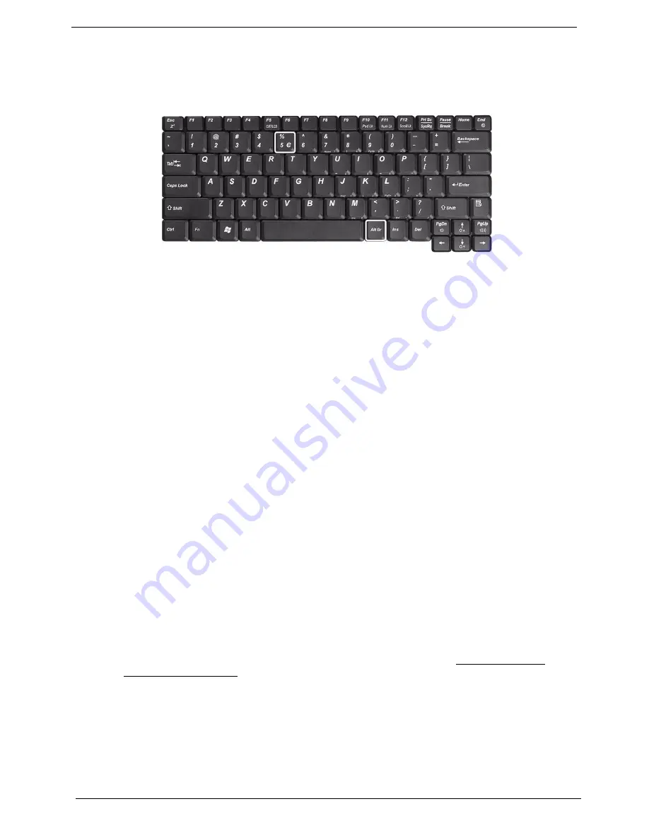
The Euro Symbol
If your keyboard layout is set to United States-International or United Kingdom or if you have a keyboard with a
European layout, you can type the Euro symbol on your keyboard.
NOTE:
For US keyboard users: The keyboard layout is set when you first set up Windows. For the Euro
symbol to work, the keyboard layout has to be set to United States-International.
To verify the keyboard type in Windows 2000 and Windows Millennium Edition, follow the steps below:
1.
Click on
Start, Settings, Control Panel
.
2.
Double-click on
Keyboard
.
3.
Click on the
Language
tab.
4.
Verify that keyboard layout used for “En English (United States)” is set to United States-International. If
not, select and click on
Properties
; then select
United States-International
and click on
OK
.
5.
Click on
OK
.
To verify the keyboard type in Windows XP, follow the steps below:
1.
Click on
Start
,
Control Panel
.
2.
Double-click on
Regional and Language Options
.
3.
Click on the
Language
tab and click on
Details
.
4.
Verify that the keyboard layout used for "En English (United States)" is set to United States-International.
If not, select and click on
ADD
; then select
United States-International
and click on
OK
.
5.
Click on
OK
.
To type the Euro symbol:
1.
Locate the Euro symbol on your keyboard.
2.
Open a text editor or word processor.
3.
Hold
Alt Gr
and press the Euro symbol.
NOTE:
Some fonts and software do not support the Euro symbol. Please refer to www.microsoft.com/
typography/faq/faq12.htm for more information.
Summary of Contents for TravelMate 290 Series
Page 6: ...VI ...
Page 44: ...36 Chapter 2 ...
Page 50: ...42 Chapter 2 ...
Page 55: ...Chapter 3 47 Removing the Battery Pack 1 Slide the battery latch 2 Then remove the battery ...
Page 58: ...50 Chapter 3 ...
Page 68: ...60 Chapter 3 ...
Page 82: ...74 Chapter 4 ...
Page 86: ...78 Chapter 5 ...
Page 88: ...80 Chapter 6 Exploded Diagram THE SYSTEM ...
Page 89: ...Chapter 6 81 LOGIC UPPER ASSY ...
Page 90: ...82 Chapter 6 LCD 14 1 ...
Page 91: ...Chapter 6 83 LCD 15 ...
Page 92: ...84 Chapter 6 OPTICAL DISC DRIVE MODULE AND COMBO DRIVE MODULE HDD ASSY ...
Page 102: ...94 Chapter 6 ...
Page 104: ...Appendix A 96 ...
Page 112: ...104 Appendix B ...
Page 114: ...106 Appendix C ...