


Chapter 2
51
Main
Parameter
Description
System Time / System
Date
The hours are displayed with 24 hours format. The values set in these two fields
take effect immediately.
System Memory
This field reports the memory size of system base memory. The size is fixed to
640KB.
Extended Memory
This field reports the memory size of the extended memory in the system.
Extended Memory size = Total memory size - 1 MB
Video Memory
VGA Memory size = 128MB
Quiet Boot
Customer Logo display will be shown during POST when it is selected.
Power on display
Auto
: During power on process, the system will detect if any display device is
connected on external video port. If any external display device is connected,
the power on display will be in CRT (or projector) only mode. Otherwise it will be
in LCD only mode.
Both
: Simultaneously enable both the integrated LCD screen and the system’s
external video port (for an external CRT or projector).
Network boot
When this is selected, Boot from LAN feature is enabled. When this is not
selected, Boot from LAN feature is then disabled.
F12 Boot Menu
When this is selected, users can modify device boot priority by pressing F12 key
during POST. When this is not selected, device boot priority will not be
adjustable during POST.
D2D Recovery
Allow user to enable/disable the Disk-to-Disk recovery
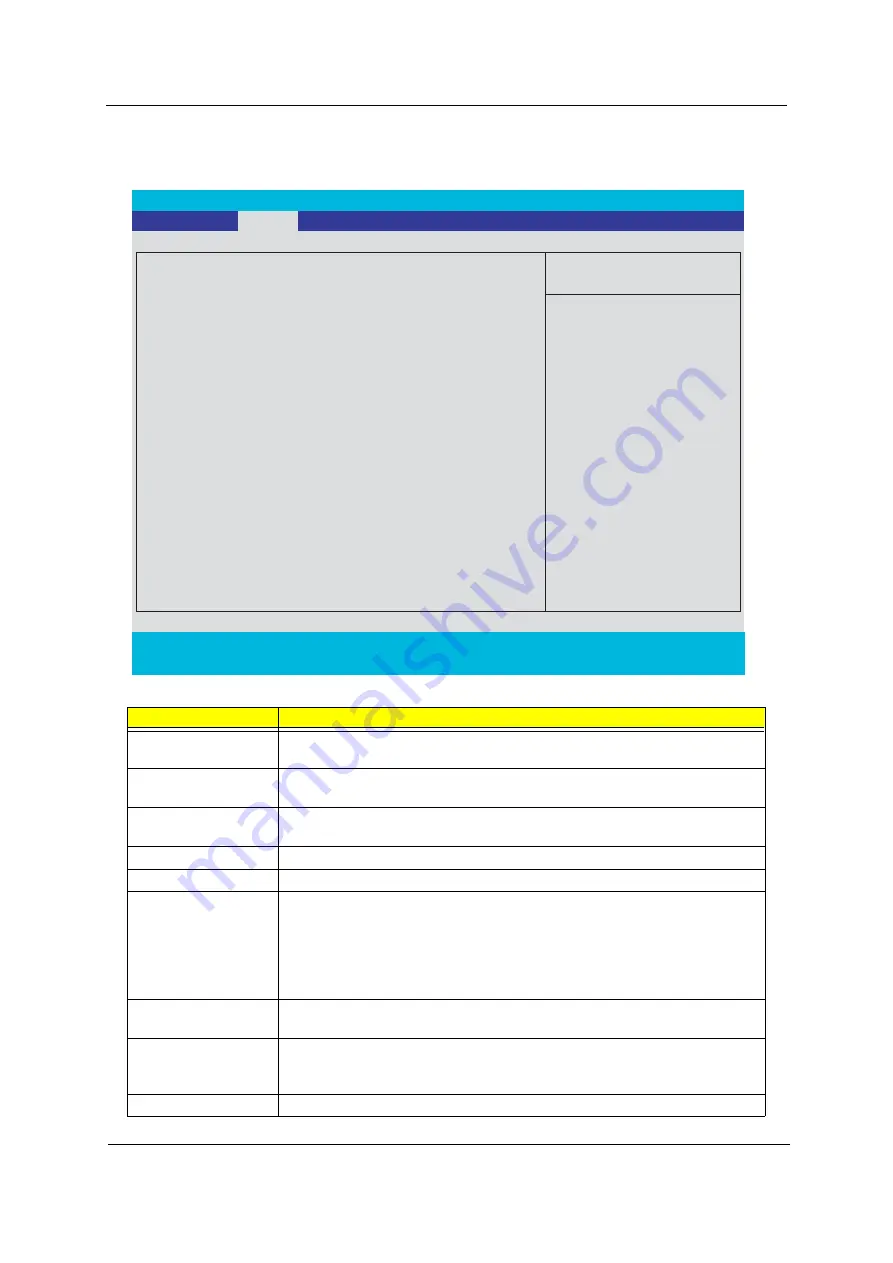
PhoenixBIOS Setup Utility
Info.
Main
Advanced Security Boot Exit
Item Specific Help
System Time:
[11:59:38]
System Date:
[02/20/2006]
System Memory:
640 KB
Extended Memory:
1022 KB
Video Memory
256 MB
Quiet Boot:
[Enabled]
Power on Display:
[Auto ]
Network boot
[Enabled]
F12 Boot Menu:
[Disabled]
[Enabled]
<Tab>, <Shift-Tab>, or
<Enter> selects field.
F1
Help
↑ ↓
Select Item
F5/F6
Change Values
F9
Setup Defaults
Esc
Exit
←
→
Select Menu
Enter
Select
4
Sub -Menu
F10
Save and Exit
D2D Recovery:
Summary of Contents for Ferrari 5000
Page 37: ...28 Chapter 1 ...
Page 98: ...Chapter 4 89 ...
Page 101: ...Chapter 5 92 Main Board Bottom Side Jumper and Connector Location Chapter 5 ...
Page 103: ...Chapter 5 94 Top Side ...
Page 118: ......