Chapter 3
77
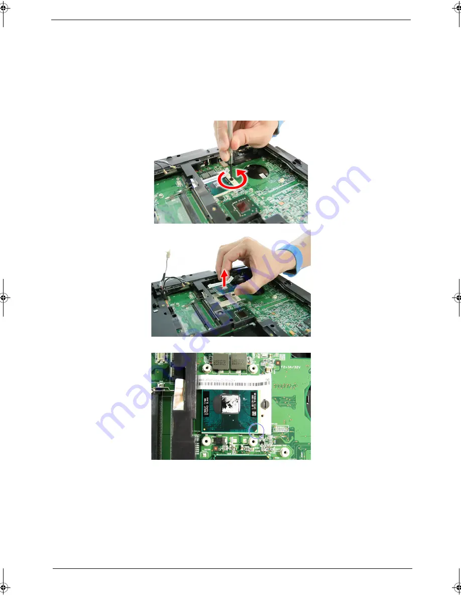
Removing the CPU
1.
See “Removing the Battery Pack” on page 62..
2.
See “Removing the Lower Cover” on page 64..
3.
See “Removing the Heatsink Fan Module” on page 74.
4.
See “Removing the CPU and VGA Heatsink Module” on page 75.
5.
Using a flat screwdriver, turn the CPU socket latch counter-clockwise to release the CPU, then remove
the CPU.
NOTE: When installing the CPU, make sure to install the CPU with PIN 1 at the corner as shown.
Removing the VGA board (for Discrete model only)
1.
See “Removing the Battery Pack” on page 62.
2.
See “Removing the Lower Cover” on page 64.
3.
See “Removing the Heatsink Fan Module” on page 74.
4.
See “Removing the CPU and VGA Heatsink Module” on page 75.
SG_Tangiz.book Page 77 Tuesday, July 10, 2007 11:01 AM
Summary of Contents for Extensa 7620
Page 6: ...VI ...
Page 10: ...X Table of Contents ...
Page 50: ...40 Chapter 1 ...
Page 67: ...Chapter 2 57 ...
Page 68: ...58 Chapter 2 ...
Page 114: ...104 Chapter 3 ...
Page 128: ...118 Chapter 4 F5h Boot to Mini DOS F6h Clear Huge Segment F7h Boot to Full DOS Code Beeps ...
Page 172: ...Appendix A 162 ...
Page 178: ...168 Appendix C ...


