


Parts of the Display and Their Functions
8
Using the Remote Control
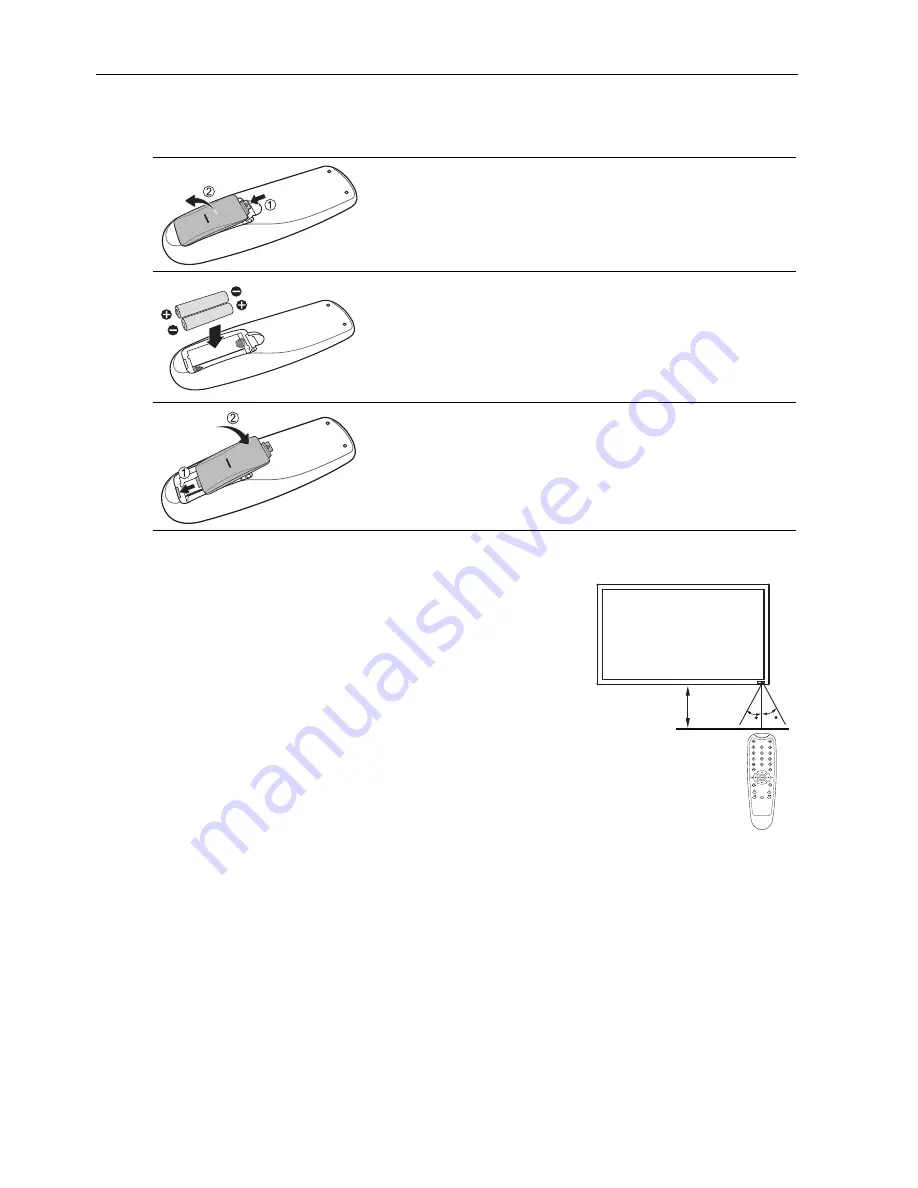
Installing Remote Control Batteries
Remote Control Usage Tips
Battery Safety Notice
Using wrong types of batteries may cause chemical leaks and/or explosion. Please
pay attention to the following notes:
• Always ensure that the batteries are inserted with the positive and negative
terminals in the correct directions as shown in the battery compartment.
• Different types of batteries have different characteristics. Do not mix different types.
Do not mix old and new batteries. Mixing old and new batteries will shorten battery
life and/or cause chemical leaks from the old batteries.
• When batteries fail to function, replace them immediately.
• Chemical leaks from batteries may cause skin irritation. If any chemical matter
seeps out of the batteries, wipe it up immediately with a dry cloth.
1. Open the remote control battery compartment cover.
2. Insert the supplied batteries ensuring that the positive
and negative marked battery terminals match the (+)
and (-) marks in the battery compartment.
Note:
The supplied batteries are provided for your convenience
so that you can operate the display straight away. You
should replace them as soon as possible.
3. Refit the battery compartment cover.
• Point and aim the top front of the remote control
directly at the display’s remote control sensor window
when you press the buttons.
• Do not let the remote control become wet or place it in
humid environments (like bathrooms).
• If the display’s remote control sensor window is
exposed to direct sunlight or strong light, the remote
control may not operate properly. In this situation,
change the light source, readjust the angle of the
display or operate the remote control from a location
closer to display’s remote control sensor window.
45
45
YPbPr
Max. 10 m
(32.8 feet)
Summary of Contents for DV650C
Page 50: ...Troubleshooting 48...


