50
Chapter 3
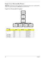
Upper Cover Disassembly Process
IMPORTANT:
This disassembly procedure represents two separate SKUs for the Aspire one; the HDD and SSD
models. The procedures outlined use the
SSD model
unless otherwise stated.
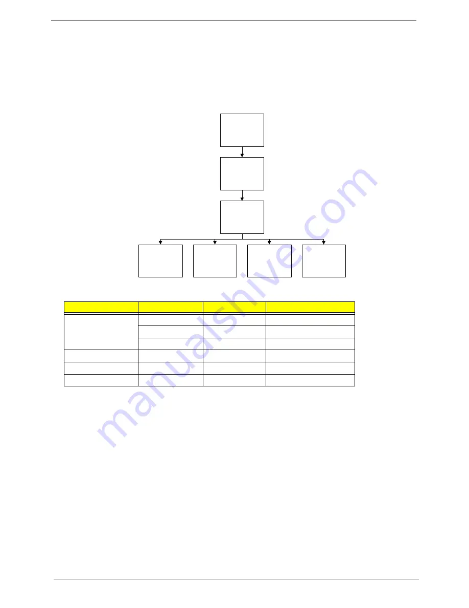
Upper Cover Disassembly Flowchart
Screw List
Step
Screw
Quantity
Part No.
Upper Cover
M2*6
3
86.S6507.001
M2*5
8
86.S0207.002
M2*3
7
86.S0207.001
Power Board
M2*2
2
86.W4107.002
Button Board
M2*3
2
86.S0207.001
LCD Module
M2*5
2
86.S0207.002
Remove External
Modules before
proceeding
Remove
LCD Module
Remove
Keyboard
Remove
Upper Cover
Remove
Button Board
Remove
Power Board
Remove
TouchPad FFC
Summary of Contents for Aspire One AO531h
Page 6: ...VI ...
Page 10: ...X Table of Contents ...
Page 30: ...20 Chapter 1 ...
Page 48: ...38 Chapter 2 ...
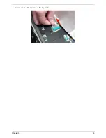
Page 63: ...Chapter 3 53 8 Disconnect the FFC and remove the Keyboard ...
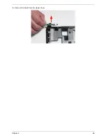
Page 69: ...Chapter 3 59 4 Remove the board from the Upper Cover ...
Page 82: ...72 Chapter 3 5 Disconnect the Bluetooth cable from the module ...
Page 89: ...Chapter 3 79 4 Lift the CPU Fan clear of the Mainboard ...
Page 101: ...Chapter 3 91 4 Lift up the bezel and remove it from the LCD Module ...
Page 107: ...Chapter 3 97 7 Disconnect the cable from the LCD panel as shown ...
Page 138: ...128 Chapter 3 6 Insert the FFC in to the Button Board and close the locking latch ...
Page 202: ...192 Appendix B ...
Page 204: ...194 Appendix C ...
Page 208: ...198 ...

