


Chapter 4
153
9.
Restore system and file settings from a known good date using
System
Restore
.
If the issue is not fixed, repeat the preceding steps and select an earlier time and date.
10.
Reinstall the Operating System.
11.
If the Issue is still not resolved, see “Online Support Information” on page 255.
Internal Microphone Failure
If the internal
Microphone
fails, perform the following actions one at a time to correct the problem. Do not
replace non-defective FRUs:
Microphone Problems
If internal or external
Microphones
do no operate correctly, perform the following actions one at a time to
correct the problem.
1.
Check that the microphone is enabled. Navigate to
Start
´
Control
Panel
´
Hardware
and
Sound
´
Sound
and select the
Recording
tab.
2.
Right-click on the
Recording
tab and select
Show
Disabled
Devices
(clear by default).
3.
The microphone appears on the
Recording
tab.
4.
Right-click on the microphone and select
Enable
.
5.
Select the microphone then click
Properties
. Select the
Levels
tab.
6.
Increase the volume to the maximum setting and click
OK
.
7.
Test the microphone hardware:
a.
Select the microphone and click
Configure
.
b.
Select
Set up microphone
.
c.
Select the microphone type from the list and click
Next
.
d.
Follow the onscreen prompts to complete the test.
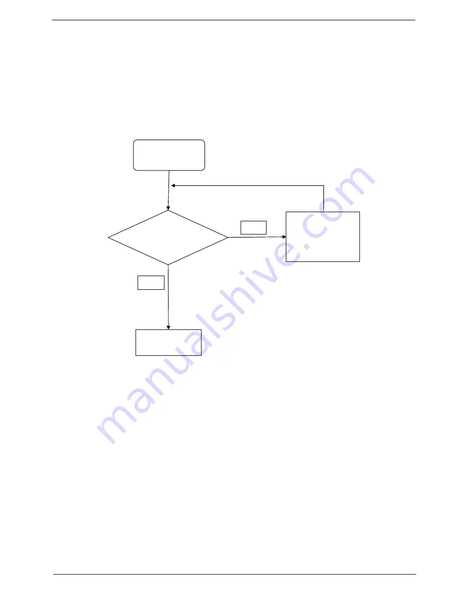
Start
Check M/B Mic.
cable
Re-assemble the
MIC cable to M/B
NG
Swap M/B
OK
Summary of Contents for Aspire 5820T Series
Page 6: ...VI ...
Page 10: ...X Table of Contents ...
Page 48: ...38 Chapter 2 ...
Page 57: ...Chapter 3 47 4 Lift the base door out and away ...
Page 62: ...52 Chapter 3 5 Pull the WLAN module out and away ...
Page 64: ...54 Chapter 3 5 Pull the 3G module out and away ...
Page 78: ...68 Chapter 3 4 Unlock and disconnect the switch board FFC ...
Page 80: ...70 Chapter 3 4 Lift the power board away ...
Page 85: ...Chapter 3 75 14 Lift the LCD module out of the assembly ...
Page 98: ...88 Chapter 3 Right Hinge Disassembly M2 5 3 2 86 PTN07 003 Step Screw Quantity Part No ...
Page 104: ...94 Chapter 3 7 Disconnect the FPC cable ...
Page 107: ...Chapter 3 97 8 Remove the cable from the retention guides 9 Pry the antenna off the casing ...
Page 112: ...102 Chapter 3 7 Lay the cables along the retention guides ...
Page 127: ...Chapter 3 117 4 Connect and lock the I O card FFC to the mainboard ...
Page 129: ...Chapter 3 119 4 Connect the Bluetooth module cable to the main board ...
Page 139: ...Chapter 3 129 7 Connect and lock the button board FFC ...
Page 147: ...Chapter 3 137 4 Grasp the tab and slide the HDD firmly into the docking connector ...
Page 150: ...140 Chapter 3 4 Push the ODD completely into the bay until flush with the lower cover ...
Page 154: ...144 Chapter 3 ...
Page 172: ...162 Chapter 4 ...
Page 176: ...166 Chapter 5 ...
Page 190: ...180 Chapter 6 ...
Page 260: ...250 Appendix A ...
Page 266: ...256 ...