


6
Chapter 1
Notebook Tour
This section provides an overview of the features and functions of the notebook.
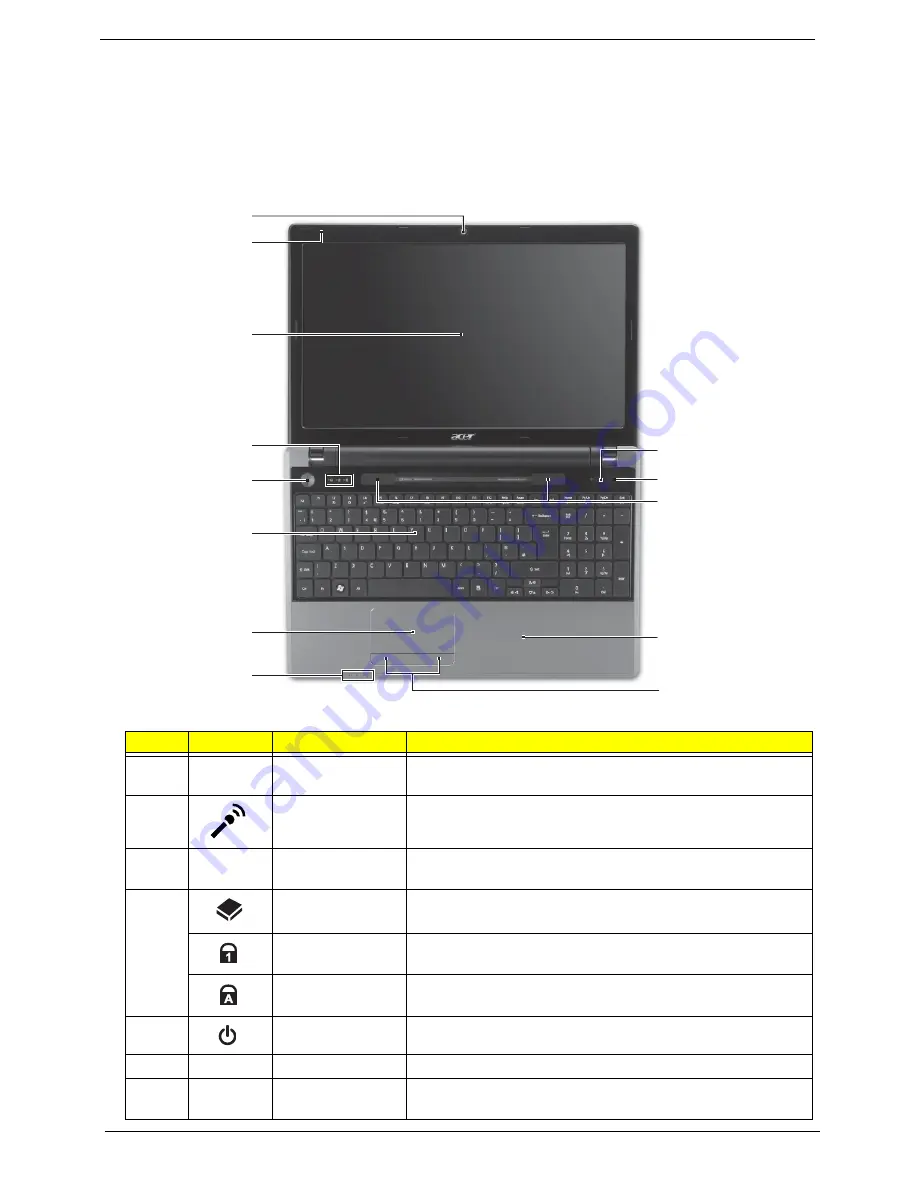
Top View
#
Icon
Item
Description
1
Acer Crystal Eye
webcam
Web camera for video communication. (only for certain
models)
2
Microphone
Internal microphone for recording sound.
3
Display screen
Also called Liquid-Crystal Display (LCD), displays computer
output (configuration may vary by model).
4
HDD indicator
Indicates when the HDD is active.
Num Lock
indicator
Lights up when the Num Lock is activated.
Caps Lock
indicator
Lights up when the Caps Lock is activated.
5
Power button/
Turns the computer on and off.
6
Keyboard
For entering data into your computer
7
Touchpad
Touch-sensitive pointing device which functions like a
computer mouse.
1
2
3
4
5
6
7
8
10
11
12
13
9
Summary of Contents for Aspire 5820T Series
Page 6: ...VI ...
Page 10: ...X Table of Contents ...
Page 48: ...38 Chapter 2 ...
Page 57: ...Chapter 3 47 4 Lift the base door out and away ...
Page 62: ...52 Chapter 3 5 Pull the WLAN module out and away ...
Page 64: ...54 Chapter 3 5 Pull the 3G module out and away ...
Page 78: ...68 Chapter 3 4 Unlock and disconnect the switch board FFC ...
Page 80: ...70 Chapter 3 4 Lift the power board away ...
Page 85: ...Chapter 3 75 14 Lift the LCD module out of the assembly ...
Page 98: ...88 Chapter 3 Right Hinge Disassembly M2 5 3 2 86 PTN07 003 Step Screw Quantity Part No ...
Page 104: ...94 Chapter 3 7 Disconnect the FPC cable ...
Page 107: ...Chapter 3 97 8 Remove the cable from the retention guides 9 Pry the antenna off the casing ...
Page 112: ...102 Chapter 3 7 Lay the cables along the retention guides ...
Page 127: ...Chapter 3 117 4 Connect and lock the I O card FFC to the mainboard ...
Page 129: ...Chapter 3 119 4 Connect the Bluetooth module cable to the main board ...
Page 139: ...Chapter 3 129 7 Connect and lock the button board FFC ...
Page 147: ...Chapter 3 137 4 Grasp the tab and slide the HDD firmly into the docking connector ...
Page 150: ...140 Chapter 3 4 Push the ODD completely into the bay until flush with the lower cover ...
Page 154: ...144 Chapter 3 ...
Page 172: ...162 Chapter 4 ...
Page 176: ...166 Chapter 5 ...
Page 190: ...180 Chapter 6 ...
Page 260: ...250 Appendix A ...
Page 266: ...256 ...