


152
Chapter 4
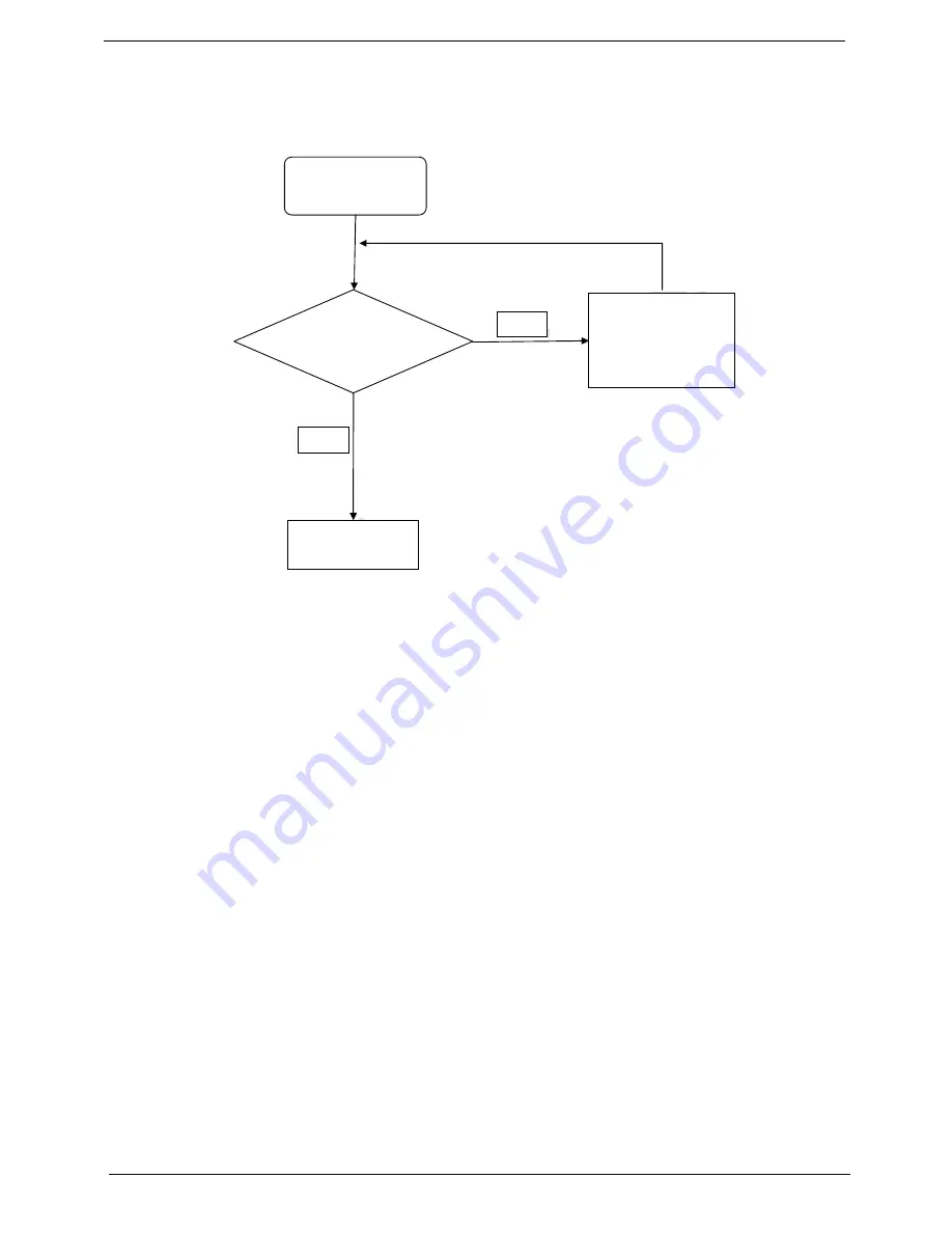
Internal Speaker Failure
If the internal
Speakers
fail, perform the following actions one at a time to correct the problem. Do not replace
non-defective FRUs:
Sound Problems
If sound problems are experienced, perform the following actions one at a time to correct the problem.
1.
Reboot the computer.
2.
Navigate to
Start
´
Control
Panel
´
System
and
Maintenance
´
System
´
Device
Manager
. Check
the Device Manager to determine that:
•
The device is properly installed.
•
There are no red Xs or yellow exclamation marks.
•
There are no device conflicts.
•
No hardware is listed under Other Devices.
3.
Roll back the audio driver to the previous version, if updated recently.
4.
Remove and reinstall the audio driver.
5.
Ensure that all volume controls are set mid range:
a.
Click the volume icon on the taskbar and drag the slider to 50. Ensure that the volume is not muted.
b.
Click Mixer to verify that other audio applications are set to 50 and not muted.
6.
Navigate to
Start
´
Control
Panel
´
Hardware
and
Sound
´
Sound
. Ensure that Speakers are selected
as the default audio device (green check mark).
NOTE:
If Speakers does not show, right-click on the
Playback
tab and select
Show
Disabled
Devices
(clear by default).
7.
Select Speakers and click
Configure
to start
Speaker
Setup
. Follow the onscreen prompts to configure
the speakers.
8.
Remove and recently installed hardware or software.
Start
Check M/B SPK
cable
Re-assemble the
SPK cable to M/B
NG
OK
Swap M/B
Summary of Contents for Aspire 5820T Series
Page 6: ...VI ...
Page 10: ...X Table of Contents ...
Page 48: ...38 Chapter 2 ...
Page 57: ...Chapter 3 47 4 Lift the base door out and away ...
Page 62: ...52 Chapter 3 5 Pull the WLAN module out and away ...
Page 64: ...54 Chapter 3 5 Pull the 3G module out and away ...
Page 78: ...68 Chapter 3 4 Unlock and disconnect the switch board FFC ...
Page 80: ...70 Chapter 3 4 Lift the power board away ...
Page 85: ...Chapter 3 75 14 Lift the LCD module out of the assembly ...
Page 98: ...88 Chapter 3 Right Hinge Disassembly M2 5 3 2 86 PTN07 003 Step Screw Quantity Part No ...
Page 104: ...94 Chapter 3 7 Disconnect the FPC cable ...
Page 107: ...Chapter 3 97 8 Remove the cable from the retention guides 9 Pry the antenna off the casing ...
Page 112: ...102 Chapter 3 7 Lay the cables along the retention guides ...
Page 127: ...Chapter 3 117 4 Connect and lock the I O card FFC to the mainboard ...
Page 129: ...Chapter 3 119 4 Connect the Bluetooth module cable to the main board ...
Page 139: ...Chapter 3 129 7 Connect and lock the button board FFC ...
Page 147: ...Chapter 3 137 4 Grasp the tab and slide the HDD firmly into the docking connector ...
Page 150: ...140 Chapter 3 4 Push the ODD completely into the bay until flush with the lower cover ...
Page 154: ...144 Chapter 3 ...
Page 172: ...162 Chapter 4 ...
Page 176: ...166 Chapter 5 ...
Page 190: ...180 Chapter 6 ...
Page 260: ...250 Appendix A ...
Page 266: ...256 ...