Chapter 1
1
Features
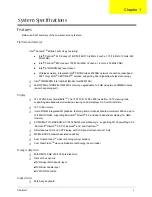
Below is a brief summary of the computer’s many feature:
Platform and memroy
Intel
®
Centrino
TM
Mobile Technology, featuring:
t
Intel
®
Pentium
®
M Processor 740/750/760/770 (2 MB L2 cache, 1.73/1.86/2/2.13 GHz, 533
MHz FSB)
t
Intel
®
Pentium
®
M Processor 735/735A (2MB L2 cache, 1.6 GHz, 400 MHz FSB)
t
Intel
®
915GM/PM Express chipset
t
Wireless solution: integrated Intel
®
PRO/Wireless 2200BG network connection (dual-band
802.11b/g) Wi-Fi
®
CERTIFIED
TM
solution, supporting Acer SignalUp wireless technology
T
Intel
®
915GM/PM+Intel ICH6-M (Mobile Intel 82801FB)
T
256/512 MB of DDR2 400/533 MHz memory, upgradeable to 2 GB using two soDIMM modules
(dual-channel support)
Display
T
14.1 WXGA Acer CrystalBrite
TM
color TFT LCD, 1280 x 800 resolution, 16:10 viewing ratio,
supporting simultaneous multi-window viewing on dual displays via Acer GridVista
TM
T
16.7 million colors
T
Intel
®
915GM integrated 3D graphics, featuring Intel
®
Graphics Media Accelerator 900 and up to
128 MB of VRAM, supporting Microsoft
®
DirectX
®
9.0 and dual independent display (for UMA
models)
T
ATI MOBILITY
TM
RADEON
TM
X1300 256/512 HyperMemory
TM
, supporting ATI PopwerPlay
TM
5.0,
, Microsoft
®
DirectX
®
9.0, PCI Express
®
and and DualView
TM
T
Simultaneous LCD and CRT display, with LCD panel refresh rate at 70 Hz
T
MPEG-2/DVD hardware-assisted capability
T
Acer CinemaVision
TM
video technology (Acer Arcade)
T
Acer ClearVision
TM
video optimization technology (Acer Arcade)
Storage subsystem
T
40/60/80/100 GB ATA/100 hard disk drive
T
Optical drive options:
t
DVD-Super Multi double-layer
t
DVD-Dual double layer
t
DVD/CD-RW combo
Input devices
T
84/85-key keyboard
System Specifications
Chapter 1
Summary of Contents for Aspire 5500
Page 6: ...VI ...
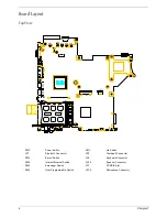
Page 14: ...6 Chapter 1 JP23 Modem Cable Connector JP39 ODD Connector ...
Page 36: ...28 Chapter 1 ...
Page 48: ...40 Chapter 2 ...
Page 57: ...Chapter 3 49 ...
Page 81: ...Chapter 5 73 JP19 RJ11 RJ45 JP31 DDR2 Socket JP23 Modem Cable Connector JP39 ODD Connector ...
Page 82: ...74 Chapter 5 ...
Page 84: ...76 Chapter 6 Exploded Diagram The System 011 012 013 ...
Page 85: ...Chapter 6 77 Upper Case Assembly ...
Page 86: ...78 Chapter 6 Lower Case Assembly ...
Page 87: ...Chapter 6 79 LCD Module ...
Page 88: ...80 Chapter 6 HDD Module ODD Module ...
Page 103: ...Index 104 ...


