26
Chapter 1
Package configuration
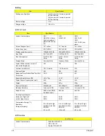
3 cells in series, 2 series in parallel
for 6-cell battery
2 cells in series, 3 series in parallel
for 9-cell battery
Normal voltage
11.1V
Charge voltage
12.6+-0.1v
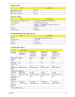
LCD 14.1 inch
Item
Specification
Vendor & model name
QDI:
QD14TL01 (Glare)
Surface treatment:
glare+hard coating
3H
QDI
QD14TL01
CMO
N141I1-L03
CMO
N141I1-L02 (non-
glare)
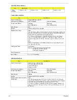
Screen Diagonal (mm)
14.1 inches
14.1 inches
14.1 inches
Active Area (mm)
303.7x189.8
303.7x189.8
303.3x189.6
Display resolution (pixels)
1280x800 WXGA
1280x800 WXGA
1280x800 WXGA
Pixel Pitch
0.2373x0.2373
0.2373x0.2373
0.2373x0.2373
Pixel Arrangement
R.G.B. Vertical
Stripe
R.G.B. Vertical
Stripe
R.G.B. Vertical
Stripe
Display Mode
Normally White
Normally White
Normally White
Typical White Luminance (cd/m
2
)
also called Brightness
185
185
185
Luminance Uniformity
1.25 (5 points)
1.25 (5 points)
N/A
Contrast Ratio
300
300
400
Response Time (Optical Rise Time/Fall
Time)msec
10/15
10/15
5/11
Nominal Input Voltage VDD
+3.3V Typ.
+3.3V
+3.3V
Typical Power Consumption (watt)
N/A
N/A
N/A
Weight
440g
440g
425g
Physical Size(mm)
320x206x5.5
320x206x5.5
320x206x5.5
Electrical Interface
1 channel LVDS
1 channel LVDS
1 channel LVDS
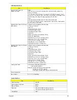
Support Color
262K colors (RGB
6-bit data driver)
262,144
262,144
Viewing Angle (degree)
Horizontal: Right/Left
Vertial: Upper/Lower
45/45
20/35
45/45
20/35
45/45
20/45
Temperature Range( C)
Operating
Storage (shipping)
0 to +40 (with high
humidity more than
90%RH)
-25 to +60
0 to +40 (with high
humidity more than
90%RH)
-25 to +60
0 to +40 (with high
humidity more than
90%RH)
-20 to +60
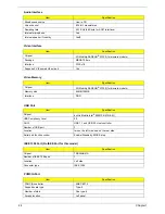
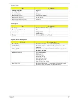
LCD Inverter
Item
Specification
Vendor & model name
Delta DAC-07B037 B
YEC YNV-C01
SumidaTWS-442-125
Battery
Item
Specification
°
Summary of Contents for Aspire 5500
Page 6: ...VI ...
Page 14: ...6 Chapter 1 JP23 Modem Cable Connector JP39 ODD Connector ...
Page 36: ...28 Chapter 1 ...
Page 48: ...40 Chapter 2 ...
Page 57: ...Chapter 3 49 ...
Page 81: ...Chapter 5 73 JP19 RJ11 RJ45 JP31 DDR2 Socket JP23 Modem Cable Connector JP39 ODD Connector ...
Page 82: ...74 Chapter 5 ...
Page 84: ...76 Chapter 6 Exploded Diagram The System 011 012 013 ...
Page 85: ...Chapter 6 77 Upper Case Assembly ...
Page 86: ...78 Chapter 6 Lower Case Assembly ...
Page 87: ...Chapter 6 79 LCD Module ...
Page 88: ...80 Chapter 6 HDD Module ODD Module ...
Page 103: ...Index 104 ...

