34
Chapter 2
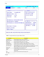
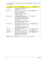
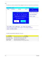
The table below describes the parameters in this screen. Settings in
boldface
are the default and suggested
parameter settings.
NOTE:
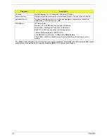
You can also enable Acer disc-to-disc system recovery via Alt+F10 during POST.
Parameter
Description
Format/Option
Date and Time
The hours are displayed with 12 hour format. The
values setin these two fields take effect
immediately.
Quiet Boot
Determines if the system will display customer
logo and summary screen or not.
Enable: Customer logo is displayed, and
summary screen is disabled.
Disabled: Custoemr logo is not displayed, and
summary screen is enabled.
Option:
Enabled
or Disabled
Power on display
Auto: During power process, the system will
detect if any display device is connected on
external video port. If any external display device
is connected, the power on display will be in CRT
(or projector) only mode. Otherwise it will be in
LCD only mode.
Both: Simultaneously enable both the integrated
LCD screen and the system’s external video port
(for an external CRT or projector).
Option:
Auto
or Both
LCD Auto Dim
Determines if the system will automatically dim
the LCD brightness in order to save power when
AC is not present.
The system will support an automatic dimming of
the LCD backlight when the AC power is NOT
available (running on battery power).
Option:
Enabled
or Disabled
Network Boot
Enables, disables the system boot from LAN
(remote server).
Option:
Enabled
or Disabled
F12 Boot Menu
Enables, disables Boot Menu during POST.
Option:
Disabled
or Enabled
D2D Recovery
Enables, disables D2D Recovery function. The
function allows the user to create a hidden
partition on hard disc drive to store operation
system and restore the system to factory
defaults.
Option:
Enabled
or Disabled
Summary of Contents for Aspire 5500
Page 6: ...VI ...
Page 14: ...6 Chapter 1 JP23 Modem Cable Connector JP39 ODD Connector ...
Page 36: ...28 Chapter 1 ...
Page 48: ...40 Chapter 2 ...
Page 57: ...Chapter 3 49 ...
Page 81: ...Chapter 5 73 JP19 RJ11 RJ45 JP31 DDR2 Socket JP23 Modem Cable Connector JP39 ODD Connector ...
Page 82: ...74 Chapter 5 ...
Page 84: ...76 Chapter 6 Exploded Diagram The System 011 012 013 ...
Page 85: ...Chapter 6 77 Upper Case Assembly ...
Page 86: ...78 Chapter 6 Lower Case Assembly ...
Page 87: ...Chapter 6 79 LCD Module ...
Page 88: ...80 Chapter 6 HDD Module ODD Module ...
Page 103: ...Index 104 ...

