


Chapter 1
25
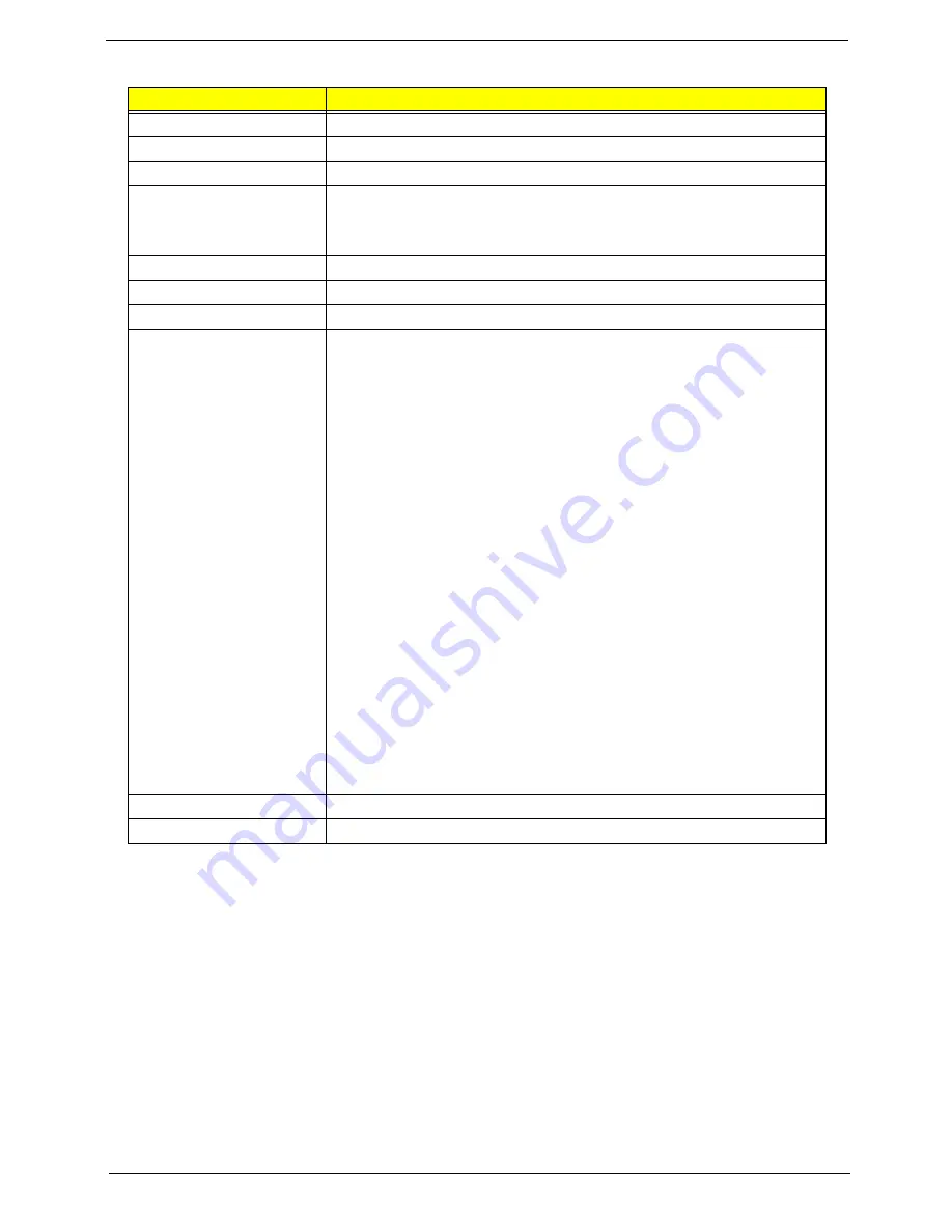
Blueray Combo Drive
Item
Specification
Manufacturer and Model
Sony NEC Optiarc BC-5500S-AR
Type
Drawer loading
Interface
SATA
Data Transfer Modes
•
PIO mode
•
DMA
•
Ultra DMA33
Buffer Memory Size
4.5 MB
Maximum Write Speed
11 Mbytes/sec
Maximum Read Speed
9 Mbytes/sec
Formats Supported
Read
•
BD-Video (12cm, Single and Dual Layer), BD-ROM (12cm, Single
and Dual Layer)
•
DVD-Video (8cm/12cm, Single and Dual Layer), DVD-ROM (8cm/
12cm, Single and Dual Layer), Multi-Boarder, Multi-Session
CD Write
•
CD-R Media (48x/40x/32x/24x/16x/8x) Mitsubishi (Verbatim), Taiyo-
Yuden, Mitsui, Ricoh, Fuji film, Sony, Hitachi Maxell, Memorex,
RITEK, CMC, P.V.C, JVC, SKC, ACER, Prime Disc, TDK
•
CD-RW Media (10x/4x) Ricoh, Mitsubishi (Verbatim), ACER,
OPTROM, Memorex, P.V.C, RITEK, CMC, LEADDATA, GigaStorage,
Prodisc, Fornex, Samsung, Philips
DVD Write
•
DVD+R Media (16x/8x/4x/2.4x) Taiyo-Yuden, Mitsubishi (Verbatim),
Ricoh, TDK
•
DVD+R Double Layer Media (8x/2.4x) Mitsubishi (Verbatim)
•
DVD+RW Media (8x/4x/2.4x) Mitsubishi (Verbatim), Ricoh, TDK
•
DVD-R Media (16x/8x/4x/2x) Mitsubishi (Verbatim), TDK, Taiyo-
Yuden, PVC, Fuji Film, Ritek
•
DVD-R DL Media (8x/4x) Mitsubishi (Verbatim)
•
DVD-RW Media (6x/4x/2x/1x) JVC, PVC, Mitsubishi (Verbatim), TDK
•
DVD-RAM Ver2.2 Media (5x/3x/2x) Panasonic, Hitachi Maxell
Power Supply
+5V (DC)
Voltage Allowance
+5V (DC) ±5%
Summary of Contents for Aspire 4937
Page 6: ...VI ...
Page 10: ...X Table of Contents ...
Page 60: ...50 Chapter 2 ...
Page 68: ...58 Chapter 3 7 Carefully open the HDD Cover ...
Page 95: ...Chapter 3 85 5 Remove the TouchPad Bracket from the Upper Base ...
Page 100: ...90 Chapter 3 5 Lift the USB Board clear of the casing ...
Page 104: ...94 Chapter 3 7 Lift the mainboard right side first to remove from the base ...
Page 112: ...102 Chapter 3 4 Lift the bezel away from the panel ...
Page 115: ...Chapter 3 105 4 Lift the LCD Panel out of the casing as shown ...
Page 122: ...112 Chapter 3 13 Ensure that the securing pin is properly located ...
Page 130: ...120 Chapter 3 7 Insert the cable through the casing to the top side as shown ...
Page 143: ...Chapter 3 133 13 Replace the two securing screws ...
Page 148: ...138 Chapter 3 4 Turn the computer over and replace the six securing screws as shown ...
Page 154: ...144 Chapter 3 ...
Page 193: ...Chapter 6 183 ...
Page 240: ...230 Appendix C ...
Page 243: ...www s manuals com ...