Chapter 5
115
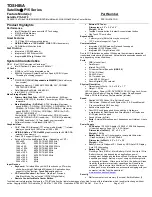
Bottom View
#
Item
#
Item
1
AC-in jack
11
5-in-1 card reader
2
Mini-card connector
12
RTC battery cable connector
3
Battery cable connector
13
Modem board
4
CPU 14
Volume
control
wheel
5
Intel PM965 Express chipset (north bridge)
15
Line-in jack
6
CRT port
16
Microphone jack
7
RJ11+RJ45 port
17
Line-out jack
8
S-video port
18
ODD connector
9
USB ports
19
HDD connector
10
1394 port
20
DIMM slot
SG_Aspire4920_Book.book Page 115 Monday, May 28, 2007 6:49 PM
Summary of Contents for Aspire 4920
Page 10: ...x ...
Page 50: ...40 Chapter 1 ...
Page 58: ...48 Chapter 2 ...
Page 94: ...84 Chapter 3 19 Carefully detach the RTC battery from the SD card slot ...
Page 105: ...Chapter 3 95 17 Remove the microphones ...
Page 106: ...96 Chapter 3 ...
Page 123: ...Chapter 5 113 System Block Diagram System Block Diagram and Connector Locations Chapter 5 ...
Page 126: ...116 Chapter 5 Switch Setting Short R525 to clear password ...
Page 130: ...120 Chapter 4 Aspire 4920 Exploded Diagram ...
Page 139: ...Chapter 4 129 ...
Page 141: ...131 Appendix A ...
Page 142: ...Appendix A 132 ...
Page 148: ...138 Appendix B ...
Page 150: ...140 Appendix C ...