System Utilities
2-19
Using DMI Tools
0
The
DMI
(Desktop Management Interface)
Tool
copies BIOS information to EEPROM
(Electrically Erasable Programmable Read-Only Memory). Used in the DMI pool for hardware
management.
LAN EEPROM Utility
0
LAN EEPROM Utility enables to change the MAC address.
Perform the following steps to use the LAN EEPROM Utility:
1.
Create a DOS bootable USB HDD.
2.
Copy the contents of the MAC folder to the HDD and remove the HDD form the computer.
3.
Reboot the computer and press
F2
during the boot sequence to enter the setup menu.
4.
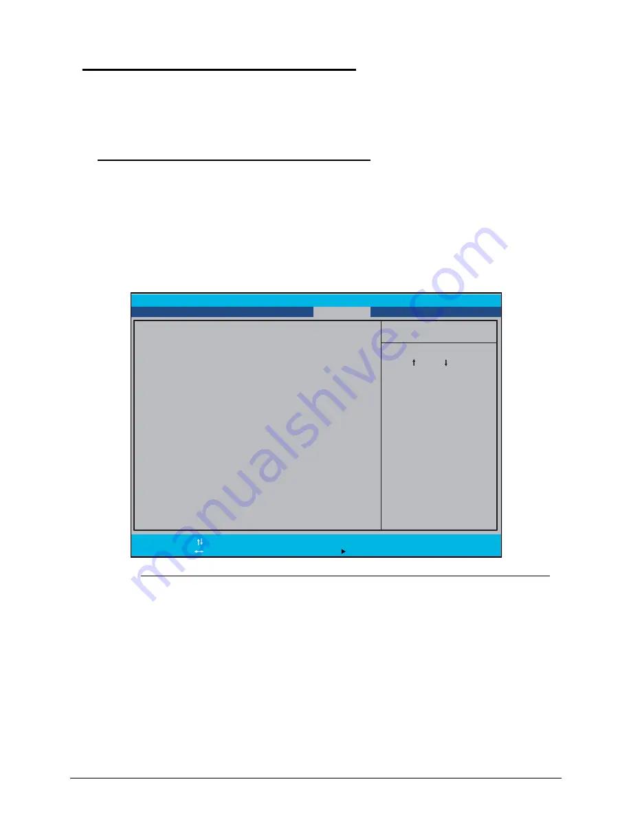
Select the Boot menu item and move the entry “USB HDD” to the first position.
Figure 2-18.
BIOS Boot
5.
Connect the USB HDD and reboot the computer.
6.
At the command prompt, navigate to the MAC folder.
7.
Execute the <
MAC.BAT
> file.
8.
At prompt type in MAC address.
9.
Press
Enter
.
10. Reboot when the process has completed.
I t e m S p e c i f i c H e l p
U s e < > o r < > t o
s e l e c t a d e v i c e , t h e n
p r e s s < F 6 > t o m o v e i t
u p t h e l i s t , o r < F 5 >
t o m o v e i t d o w n t h e
l i s t . P r e s s < E s c > t o
e s c a p e t h e m e n u .
B o o t P r i o r i t y O r d e r
F1
Esc
H e l p
E x i t
S e l e c t I t e m
S e l e c t M e n u
C h a n g e Va l u e s
S e l e c t S u b - M e n u
F5/F6
Enter
F9
F10
S e t u p D e f a u l t s
S a v e a n d E x i t
1 : I D E 0 : X X X X X X X X X X X X X X X X
2 : I D E C D / D V D : X X X X X X X X X X X X X X X X X X
3 : N e t w o r k B o o t : X X X X X X X X X X X X X X X
4 :
:
5 : U S B F D D :
6 : U S B C D / D V D :
U S B H D D
B o o t
E x i t
M a i n
I n f o r m a t i o n
S e c u r i t y
P h o e n i x S e c u r e C o r e ( t m ) S e t u p U t i l i t y
Summary of Contents for Aspire 4743
Page 1: ... Aspire 4743 4743G 4743Z 4743ZG SERVICEGUIDE ...
Page 10: ...10 ...
Page 11: ...CHAPTER 1 Hardware Specifications ...
Page 14: ...1 4 ...
Page 50: ...1 40 Hardware Specifications and Configurations ...
Page 51: ...CHAPTER 2 System Utilities ...
Page 70: ...2 20 System Utilities ...
Page 71: ...CHAPTER 3 Machine Maintenance ...
Page 74: ...3 4 ...
Page 82: ...3 12 Machine Maintenance 4 Lift the base door to remove Figure 3 9 Base Door ...
Page 85: ...Machine Maintenance 3 15 6 Detach the bracket from the HDD Figure 3 14 HDD Bracket ...
Page 87: ...Machine Maintenance 3 17 4 Pull the WLAN module out of the slot Figure 3 17 WLAN Module ...
Page 100: ...3 30 Machine Maintenance 6 Lift the speakers from the upper cover Figure 3 40 Speaker Cable ...
Page 106: ...3 36 Machine Maintenance 4 Lift the USB board from the lower cover Figure 3 50 USB Board ...
Page 174: ...3 104 Machine Maintenance ...
Page 175: ...CHAPTER 4 Troubleshooting ...
Page 207: ...CHAPTER 5 Jumper and Connector Locations ...
Page 215: ...CHAPTER 6 FRU List ...
Page 216: ...6 2 Aspire 4743 4743G 4743Z 4743ZG Exploded Diagrams 6 4 Main Assembly 6 4 LCD Assembly 6 5 ...
Page 234: ...6 20 FRU List ...
Page 235: ...CHAPTER 7 Model Definition and Configuration ...
Page 236: ...7 2 Aspire 4743 4743G 4743Z 4743ZG 7 3 ...
Page 270: ...7 36 Model Definition and Configuration ...
Page 338: ...7 104 Model Definition and Configuration ...
Page 339: ...CHAPTER 8 Test Compatible Components ...
Page 340: ...8 2 Microsoft Windows 7 Environment Test 8 4 ...
Page 351: ...CHAPTER 9 Online Support Information ...
Page 352: ...9 2 Introduction 9 3 ...
Page 354: ...9 4 Online Support Information ...


