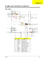
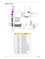


Chapter 6
171
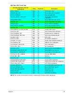
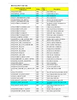
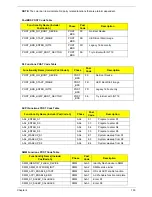
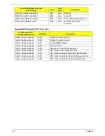
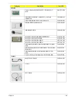
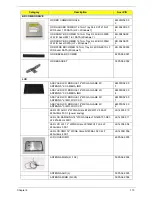
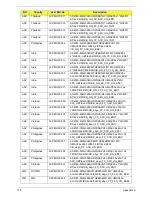
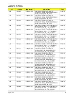
MIDDLE COVER
60.PAA02.004
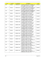
TOUCHPAD BRACKET
33.PAA02.004
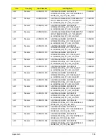
FINGER PRINT BRACKET
33.PAA02.005
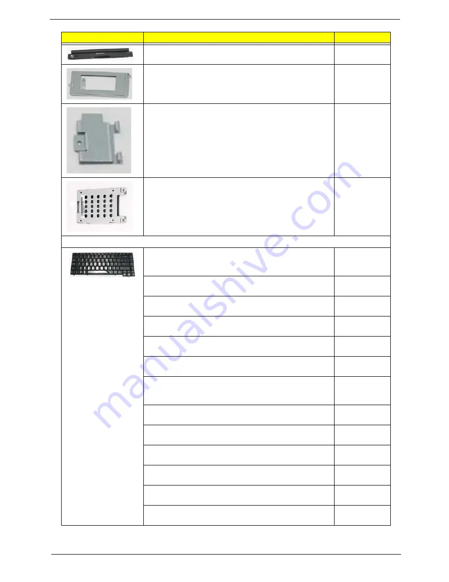
HDD BRACKET - FOR 6 LAYERS MB
33.PG502.001
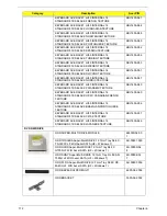
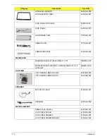
KEYBOARD
KEYBOARD ACER AC4T JV40 INTERNAL 14
STANDARD 86KS BLACK US INTERNATIONAL
TEXTURE
KB.I140A.058
KEYBOARD ACER AC4T JV40 INTERNAL 14
STANDARD 86KS BLACK GREEK TEXTURE
KB.I140A.043
KEYBOARD ACER AC4T JV40 INTERNAL 14
STANDARD 86KS BLACK ARABIC TEXTURE
KB.I140A.034
KEYBOARD ACER AC4T JV40 INTERNAL 14
STANDARD 86KS BLACK CHINESE TEXTURE
KB.I140A.038
KEYBOARD ACER AC4T JV40 INTERNAL 14
STANDARD 86KS BLACK RUSSIAN TEXTURE
KB.I140A.050
KEYBOARD ACER AC4T JV40 INTERNAL 14
STANDARD 86KS BLACK THAILAND TEXTURE
KB.I140A.055
KEYBOARD ACER AC4T JV40 INTERNAL 14
STANDARD 86KS BLACK US INTERNATIONAL W/
HEBREW TEXTURE
KB.I140A.059
KEYBOARD ACER AC4T JV40 INTERNAL 14
STANDARD 87KS BLACK UK TEXTURE
KB.I140A.057
KEYBOARD ACER AC4T JV40 INTERNAL 14
STANDARD 87KS BLACK GERMAN TEXTURE
KB.I140A.042
KEYBOARD ACER AC4T JV40 INTERNAL 14
STANDARD 87KS BLACK SWISS/G TEXTURE
KB.I140A.054
KEYBOARD ACER AC4T JV40 INTERNAL 14
STANDARD 87KS BLACK BELGIUM TEXTURE
KB.I140A.035
KEYBOARD ACER AC4T JV40 INTERNAL 14
STANDARD 87KS BLACK DANISH TEXTURE
KB.I140A.039
KEYBOARD ACER AC4T JV40 INTERNAL 14
STANDARD 87KS BLACK ITALIAN TEXTURE
KB.I140A.045
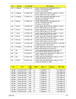
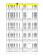
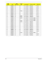
Category
Description
Acer P/N
Summary of Contents for Aspire 4740G
Page 6: ...VI ...
Page 10: ...X Table of Contents ...
Page 56: ...46 Chapter 2 ...
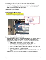
Page 63: ...Chapter 3 53 5 Carefully open the HDD Cover ...
Page 65: ...Chapter 3 55 5 Remove two 2 screws from the WLAN bracket and lift it clear of the device ...
Page 90: ...80 Chapter 3 5 Remove the TouchPad Bracket from the Upper Cover ...
Page 92: ...82 Chapter 3 Step Size Quantity Screw Type Media Board M2 5 3 2 ...
Page 97: ...Chapter 3 87 Step Size Quantity Screw Type Bluetooth Module M2 5 3 1 ...
Page 99: ...Chapter 3 89 7 Lift one edge of the mainboard as shown to remove it from the base ...
Page 107: ...Chapter 3 97 4 Lift the bezel away from the panel ...
Page 110: ...100 Chapter 3 4 Lift the LCD Panel out of the casing as shown ...
Page 117: ...Chapter 3 107 13 Ensure that the securing pin is properly located ...
Page 129: ...Chapter 3 119 ...
Page 134: ...124 Chapter 3 4 Turn the computer over Replace the fifteen screws on the bottom panel ...
Page 141: ...Chapter 3 131 4 Turn the computer over and replace the six 6 securing screws as shown ...
Page 186: ...176 Chapter 6 ...
Page 187: ...Chapter 6 177 ...
Page 208: ...Appendix A 198 ...
Page 214: ...204 Appendix B ...
Page 216: ...206 Appendix C ...


