Chapter 4
119
No Display Issue
If the
Display
doesn’t work, perform the following actions one at a time to correct the problem. Do not replace
a non-defective FRU:
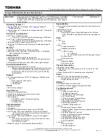
No POST or Video
If the POST or video doesn’t display, perform the following actions one at a time to correct the problem.
1.
Make sure that the internal display is selected. On this notebook model, switching between the internal
display and the external display is done by pressing
Fn+F5
. Reference Product pages for specific model
procedures.
2.
Make sure the computer has power by checking at least one of the following occurs:
•
Fans start up
•
Status LEDs light up
If there is no power, see “Power On Issue” on page 118.
3.
Drain any stored power by removing the power cable and battery and holding down the power button for
10 seconds. Reconnect the power and reboot the computer.
4.
Connect an external monitor to the computer and switch between the internal display and the external
display is by pressing
Fn+F5
(on this model).
If the POST or video appears on the external display, see “LCD Failure” on page 121.
5.
Disconnect power and all external devices including port replicators or docking stations. Remove any
memory cards and CD/DVD discs. Restart the computer.
If the computer boots correctly, add the devices one by one until the failure point is discovered.
6.
Reseat the memory modules.
7.
Remove the drives (see “Disassembly Process” on page 49).
8.
If the Issue is still not resolved, see “Online Support Information” on page 209.
START
Power On?
No
goto no power
trouble shooting
step
Replace
Ext. DDR RAM
module
No
No
Screw it well
Replace
M/B
Connect
it well
No
LCD module
OK?
No
Replace
LCD panel/
LCD cable
Ext. DDRRAM
module well
connected?
Ext. DDRRAM
module OK?
CPU thermal
module well
screw?
Summary of Contents for Aspire 4738
Page 6: ...VI ...
Page 10: ...X Table of Contents ...
Page 109: ...Chapter 3 101 5 Connect the fan cable as shown ...
Page 123: ...Chapter 3 115 4 Press down as indicated to secure the keyboard in place ...
Page 146: ...138 Chapter 4 ...
Page 150: ...142 Chapter 5 Clear CMOS Jumper Item Description J1 J2 Clear CMOS Jumper ...
Page 152: ...144 Chapter 5 ...
Page 167: ...Chapter 6 159 ...
Page 216: ...208 Appendix B ...
Page 218: ...210 Appendix C ...