


Machine Maintenance Procedures
3-47
3.
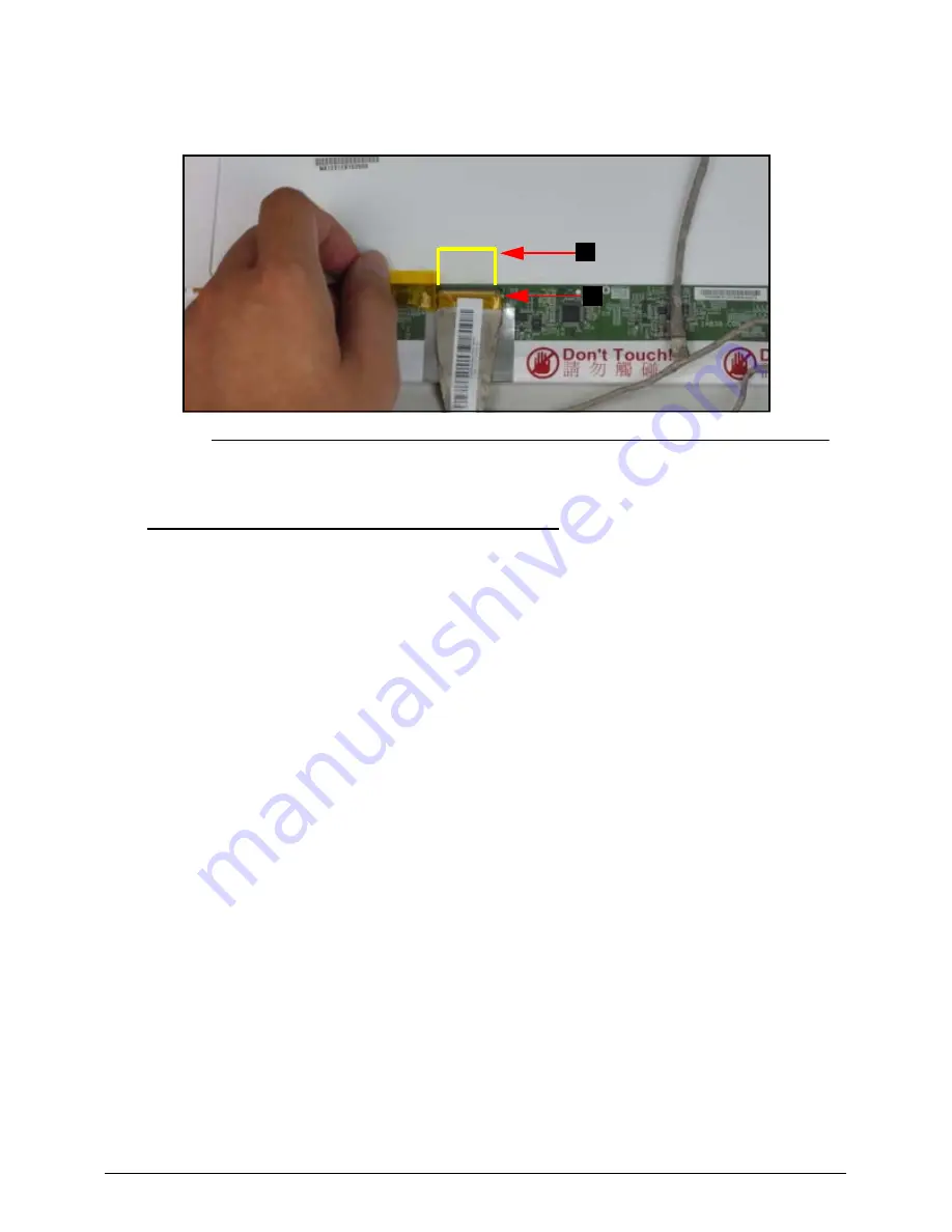
Starting from the top, remove the clear mylar tape (C) and disconnect the LVDS cable
from the LCD panel connector (D) (
Figure 3-47
)
.
Figure 3-47.
LVDS Cable
LVDS Cable Installation
0
1.
Place LVDS cable into the LCD panel connector (D) and secure clear mylar tape (C)
(
Figure 3-47
).
2.
Adhere the yellow tape (B) to the LVDS cable connector to secure it. Refer to
Figure 3-46
.
3.
Place LVDS cable (A) on the rear of the LCD panel. Refer to
Figure 3-45
.
4.
Install LCD panel.
C
D
Summary of Contents for Aspire 4349
Page 1: ...Aspire 4349 4749 4749Z SERVICEGUIDE ...
Page 10: ...x Online Support Information Introduction 9 3 ...
Page 11: ...CHAPTER 1 Hardware Specifications ...
Page 14: ...1 4 ...
Page 60: ...1 50 Hardware Specifications and Configurations ...
Page 61: ...CHAPTER 2 System Utilities ...
Page 89: ...CHAPTER 3 Machine Maintenance Procedures ...
Page 92: ...3 4 ...
Page 136: ...3 48 Machine Maintenance Procedures ...
Page 137: ...CHAPTER 4 Troubleshooting ...
Page 143: ...Troubleshooting 4 7 9 If the issue is still not resolved refer to Online Support Information ...
Page 161: ...CHAPTER 5 Jumper and Connector Locations ...
Page 168: ...5 8 Jumper and Connector Locations ...
Page 169: ...CHAPTER 6 FRU Field Replaceable Unit List ...
Page 170: ...6 2 Exploded Diagrams 6 4 FRU List 6 7 Screw List 6 16 ...
Page 185: ...CHAPTER 7 Model Definition and Configuration ...
Page 186: ...7 2 Acer Aspire 4349 7 3 Acer Aspire 4749 4749Z 7 16 ...
Page 208: ...7 24 Model Definition and Configuration ...
Page 209: ...CHAPTER 8 Test Compatible Components ...
Page 210: ...8 2 Microsoft Windows 7 Environment Test 8 4 ...
Page 220: ...8 12 Test Compatible Components ...
Page 221: ...CHAPTER 9 Online Support Information ...
Page 222: ...9 2 Introduction 9 3 ...