background image

76

Chapter 3

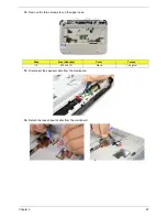
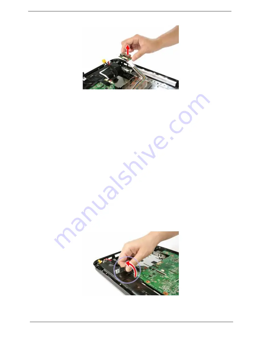
18.

Remove the USB board.

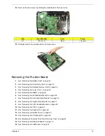
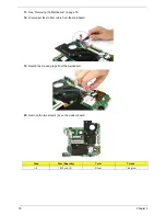
Removing the Mainboard

1.

See “Removing the Battery Pack” on page 51.

2.

See “Removing the SD Dummy Card” on page 52.

3.

See “Removing the Express Dummy Card” on page 52.

4.

See “Removing the Lower Cover” on page 53.

5.

See “Removing the DIMM” on page 54.

6.

See “Removing the WLAN Board Module” on page 55.

7.

See “Removing the Hard Disk Drive Module” on page 56.

8.

See “Removing the Optical Drive Module” on page 57.

9.

See “Removing the CPU Heatsink Module” on page 60.

10.

See “Removing the CPU” on page 61.

11.

See “Removing the Keyboard” on page 62.

12.

See “Removing the Middle Cover” on page 63.

13.

See “Removing the LCD Module” on page 64.

14.

See “Separating the Upper Case from the Lower Case” on page 66.

15.

See “Removing the Bluetooth Board” on page 73.

16.

See “Removing the USB board” on page 74.

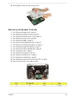
17.

Detach the power board cable from the lower case.

Summary of Contents for Aspire 4310

Page 1: ...Acer Aspire 4710 4310 Service Guide PRINTED IN TAIWAN Service guide files and updates are available on the ACER CSD web for more information please refer to http csd acer com tw ...

Page 2: ...ii Revision History Please refer to the table below for the updates made on Travelmate 4720 4320 service guide Date Chapter Updates ...

Page 3: ...ublication may be reproduced transmitted transcribed stored in a retrieval system or translated into any language or computer language in any form or by any means electronic mechanical magnetic optical chemical manual or otherwise without the prior written permission of Acer Incorporated ...

Page 4: ... sold or licensed as is Should the programs prove defective following their purchase the buyer and not Acer Incorporated its distributor or its dealer assumes the entire cost of all necessary servicing repair and any incidental or consequential damages resulting from any defect in the software Acer is a registered trademark of Acer Corporation Intel is a registered trademark of Intel Corporation C...

Page 5: ... bits and pieces of additional information related to the current topic WARNING Alerts you to any damage that might result from doing or not doing specific actions CAUTION Gives precautionary measures to avoid possible hardware or software problems IMPORTANT Reminds you to do specific actions relevant to the accomplishment of procedures ...

Page 6: ...l NOT be covered in this generic service guide In such cases please contact your regional offices or the responsible personnel channel to provide you with further technical details 2 Please note WHEN ORDERING FRU PARTS that you should check the most up to date information available on your regional web or channel If for whatever reason a part number change is made it will not be noted in the print...

Page 7: ... Management 23 Acer eDataSecurity Management 24 Acer eLock Management 25 Acer eRecovery Management 26 Acer eSettings Management 27 Windows Mobility Center 28 Using the System Utilities 29 Acer GridVista dual display compatible 29 Launch Manager 30 Norton Internet Security 31 Hardware Specifications and Configurations 32 System Utilities 39 BIOS Setup Utility 39 Entering BIOS Setup 39 BIOS Setup Pr...

Page 8: ...Board Module 72 Removing the Bluetooth Board 73 Removing the USB board 74 Removing the Mainboard 76 Removing the Modem Board 77 Removing the RTC Battery 79 LCD Module Disassembly Process 81 LCD Module Disassembly Flowchart 81 Removing the LCD Bezel 82 Removing the Inverter Board 83 Removing the LCD with Brackets 84 Removing the LCD Brackets 87 Removing the LCD Module Hinges 87 Removing the Antenna...

Page 9: ...310 Exploded Diagram 116 Aspire 4710 FRU List 117 Aspire 4710G FRU List 126 Aspire 4310 FRU List 135 Model Definition and Configuration 144 Aspire 4710 4310 144 Test Compatible Components 147 Microsoft Windows Vista Compatibility Test 148 Online Support Information 153 ...

Page 10: ...x ...

Page 11: ...memory supporting Microsoft DirectX 9 and PCI Express T Dual independent display support T 16 7 million colors T MPEG 2 DVD hardware assisted capability full decode T S video TV out NTSC PAL support T Acer Arcade featuring Acer CinemaVision and Acer ClearVision technologies Storage Subsystem T 80 120 160 GB or larger hard disk drive T DVD Super Multi double layer drive T 5 in 1 card reader support...

Page 12: ...supporting Acer SignalUp wireless technology T WPAN Bluetooth 2 0 EDR Enhanced Data Rate for selected models T LAN Gigabit Ethernet Wake on LAN ready T Modem 56K ITU V 92 with PTT approval Wake on Ring ready I O Interface T ExpressCard 54 slot T 5 in 1 card reader SD MMC MS MS PRO xD T Four USB 2 0 ports T IEEE 1394 port T External display VGA port T S video TV out NTSC PAL port T Headphones speak...

Page 13: ...es T Weight approximately with 6 cell battery 2 65 kg 6 0 lbs configuration may vary by models Environment T Temperature t Operating 5 C to 35 C t Non operating 20 C to 65 C T Humidity non condensing t operating 20 to 80 t Non operating 20 to 80 ...

Page 14: ...ng key Launch Acer Empowering Technology 6 Easy launch buttons Buttons for launching frequently used programs 7 Palmrest Comfortable support area for your hands when you use the computer 8 Status indicators Light Emitting Diodes LEDs that light up to show the status of the computer s functions and components 9 Click buttons left center and right The left and right buttons function like the left an...

Page 15: ...e audio out 2 Latch Locks and releases the lid 3 Line in jack Accepts audio line in devices e g audio CD player stereo walkman mp3 player 4 Microphone jack Accepts inputs from external microphones 5 Headphones speaker line out jack with S PDIF support Connects to audio line out devices e g speakers headphones ...

Page 16: ...cts to an Ethernet 10 100 1000 based network 5 S video TV out NTSC PAL port Connects to a television or display device with S video input 6 2 USB 2 0 ports Connect to USB 2 0 devices e g USB mouse USB camera 7 4 pin IEEE 1394 port Connects to IEEE 1394 devices 8 ExpressCard 54 slot Accepts one ExpressCard 54 module 9 5 in 1 card reader Accepts Secure Digital SD MultiMediaCard MMC Memory Stick MS M...

Page 17: ...al drive is active 3 Optical drive eject button Ejects the optical disk from the drive 4 Emergency eject hole Ejects the optical drive tray when the computer is turned off 5 USB 2 0 ports Connect to USB 2 0 devices e g USB mouse USB camera 6 DC in jack Connects to an AC adapter Item Description 1 Ventilation slots Enable the computer to stay cool even after prolonged use ...

Page 18: ...battery for removal 3 Battery lock Locks the battery in position 4 Memory compartment Houses the computer s main memory 5 Hard disk bay Houses the computer s hard disk secured with screws 6 Ventilation slots and cooling fan Enable the computer to stay cool even after prolonged use Note Do not cover or obstruct the opening of the fan ...

Page 19: ...losed up NOTE Battery LED status during charging Amber Charging Green Charging complete Icon Function Description Power Indicates the computer s power status Battery Indicates the computer s batttery status HDD Indicates when the hard disk drive is active Num lock Lights up when Num Lock is activated Caps lock Lights up when Caps Lock is activated ...

Page 20: ...l and programmable buttons run the Acer Launch Manager Icon Function Description Wireless communication button indicator Enables disables the wireless function Indicates the status of wireless LAN communication Web browser Internet browser user Programmable Mail Email application user Programmable Bluetooth communication button indicator Enables disables the Bluetooth function Indicates the status...

Page 21: ... the cursor T Press the left 1 and right 4 buttons located beneath the touchpad to perform selection and execution functions These two buttons are similar to the left and right buttons on a mouse Tapping on the touchpad is the same as clicking the left button T Use the 4 way scroll 3 button for selected models or Acer BioProtect fingerprint reader 3 supporting Acer FingerNav 4 way control function...

Page 22: ...be disabled under Mouse settings in Windows Control Panel Function Left Button 1 Right Button 4 Main touchpad 2 Center button 3 Execute Click twice quickly Tap twice at the same speed as double clicking the mouse button Select Click once Tap once Drag Click and hold then use finger to drag the cursor on the touchpad Tap twice at the same speed as double clicking a mouse button then hold finger to ...

Page 23: ...are in uppercase Num Lock Fn F11 When Num Lock is on the embedded keypad is in numeric mode The keys function as a calculator complete with the arithmetic operators and Use this mode when you need to do a lot of numeric data entry A better solution would be to connect an external keypad Scroll Lock Fn F12 When Scroll Lock is on the screen moves one line up or down when you press the up or down arr...

Page 24: ...work domain M Minimizes all windows R Open the Run dialog box T Cycle through programs on the taskbar U Open Ease of Access Center X Open Windows Mobility Center BREAK Display the System Properties dialog box SHIFT M Restore minimized windows to the desktop TAB Cycle through programs on the taskbar by using Windows Flip 3 D SPACEBAR Bring all gadgets to the front and select Windows Sidebar CTRL F ...

Page 25: ...r ePower Management Launches the Acer ePowerManagement in Acer eManager Fn F4 Sleep Puts the computer in Sleep mode Fn F5 Display toggle Switches display output between the display screen external monitor if connected and both Fn F6 Screen blank Turns the display screen backlight off to save power Press any key to return Fn F7 Touchpad toggle Turns the internal touchpad on and off Fn F8 Speaker to...

Page 26: ...Alt Gr and then press the 5 key at the upper center of the keyboard NOTE Some fonts and software do not support the Euro symbol Please refer to www microsoft com typography faq faq12 htm for more information The US dollar sign 1 Open a text editor or word processor 2 Either press at the bottom right of the keyboard or hold Shift and then press the 4 key at the upper center of the keyboard NOTE Thi...

Page 27: ...ia T Acer eRecovery Management backs up and recovers data flexibly reliably and completely T Acer eSettings Management accesses system information and adjusts settings easily For more information right click on the Empowering Technology toolbar then select the Help or Tutorial function Empowering Technology Password Before using Acer eLock Management and Acer eRecovery Management you must initiali...

Page 28: ...t Management from the Empowering Technology toolbar or run the program from the Acer Empowering Technology program group in Start menu You can also set Acer eNet Management to start automatically when you boot up your PC Acer eNet Management automatically detects the best settings for a new location while offering you the option to manually adjust the settings to match your needs ...

Page 29: ...h to the appropriate profile when you move from one location to another Settings stored include network connection settings IP and DNS settings wireless AP details etc as well as default printer settings Security and safety concerns mean that Acer eNet Management does not store username and password information ...

Page 30: ...r plans To create a new power plan Creating customized power plans allows you to save and quickly switch to a personalized set of power options 1 Click the Create Power Plan icon 2 Enter a name for your new power plan 3 Choose a predefined power plan to base your customized plan on 4 If necessary change the display and sleep settings you want your computer to use 5 Click OK to save your new power ...

Page 31: ...pter 1 21 Battery status For real time battery life estimates based on current usage refer to the panel in the upper half of the window Click the to view estimated battery life in sleep and hibernate modes ...

Page 32: ...control the enhanced sound effects of Dolby Home Theater on your system Select Movie or Game mode to experience the awesome realism of 5 1 channel surround sound from just 2 speakers via Dolby Virtual Speaker technology Music mode lets you enjoy your favorite tunes in vivid detail ...

Page 33: ...be automatically switched out when an external display is connected to the system For projectors and external devices that are not auto detected launch Acer ePresentation Management to choose an appropriate display setting NOTE If the restored resolution is not correct after disconnecting a projector or you need to use an external resolution that is not supported by Acer ePresentation Management a...

Page 34: ...The Acer eDataSecurity Management setup wizard will prompt you for a supervisor password and default encryption password This password will be used to encrypt files by default or you can choose to enter your own password when encrypting a file NOTE The password used to encrypt a file is the unique key that the system needs to decrypt it If you lose the password the supervisor password is the only ...

Page 35: ...hat can be mounted as a file system when plugged into the system T Optical Drive Devices includes any kind of CD ROM DVD ROM HD DVD or Blu ray drive devices T Floppy Drive Devices 3 5 inch floppy drives only To use Acer eLock Management the Empowering Technology password must be set first Once set you can apply locks to any of the devices types Lock s will immediately be set without any reboot nec...

Page 36: ...ps to hard disk or optical disc T Creation of backups t Factory default image t User backup image t Current system configuration t Application backup T Restore and recovery t Factory default image t User backup image t From previously created CD DVD t Reinstall applications drivers NOTE If your computer did not come with a Recovery CD or System CD please use Acer eRecovery Management s System back...

Page 37: ...allows you to inspect hardware specifications set BIOS passwords and modify boot options Acer eSettings Management also T Provides a simple graphical user interface for navigation T Prints and saves hardware specifications T Lets you set an asset tag for your system ...

Page 38: ...eless networking on off external display settings display orientation and synchronization status Windows Mobility Center also includes Acer specific settings like Bluetooth Add Device if applicable sharing folders overview sharing service on or off and a shortcut to the Acer user guide drivers and utilities To launch Windows Mobility Center T Use the shortcut key X T Start Windows Mobility Center ...

Page 39: ...ss Acer GridVista is a handy utility that offers four pre defined display settings so you can view multiple windows on the same screen To access this function please go to Start All Programs and click on Acer GridVista You may choose any one of the four display settings indicated below Double vertical Triple primary at left Triple primary at right or Quad Acer Gridvista is dual display compatible ...

Page 40: ... monitor is set to the manufacturer s recommended value Launch Manager Launch Manager allows you to set the four easy launch buttons located above the keyboard You can access the Launch Manager by clicking on Start All Programs and then Launch Manager to start the application ...

Page 41: ...Scan to scan your system 4 When the scan is complete review the results of the scan NOTE For optimal security run a Full System Scan when scanning your computer for the first time You can schedule customized virus scans that run unattended on specific dates and times or at periodic intervals If you are using the computer when the scheduled scan begins it runs in the background so that you do not h...

Page 42: ...ard Major Chips Item Specification System core logic Intel 945PM Express Intel ICH7M chipsets HDD controller Intel ICH7M chipset Memory controller Intel 945PM Express chipset Video controller Intel 945PM Express chipset Audio controller Codec ALC268 PCMCIA controller OZ129 LAN controller Intel ICH7M Broadcom 5787MKMLG chipsets Modem controller Intel ICH7M chipset Bluetooth controller Intel ICH7M c...

Page 43: ...ntegrity Service Application Program Interface BIS 1 0 PC2002 2005 compliant Intel Enhanced SpeedStep Technology Intel DPST support ASF 2 0 TPM v1 2 AHCI support iAMT 2 5 System Memory Item Specification Memory controller Intel 945PM Express chipset DIMM socket number 2 sockets Supports maximum memory size 2 GB for 32 bit OS 4 GB for 64bit OS Vendor Samsung Hynix Nanya Powerchip Promos Model name ...

Page 44: ...ort ASF 2 0 Wireless LAN module Item Specification Vendor Intel Foxconn Model name Wireless WiFi Link 4965AGN PRO Wireless 3945ABG PRO Wireless 3945BG Broadcom 4311 Data throughput 54 Mbps Protocol 802 11a b g 802 11 a b g 802 11 b g 802 11 b g Interface PCI bus mini PCI socket for wireless module Modem Item Specification Modem controller Intel 945PM Express chipset Vendor Liteon Foxconn Model nam...

Page 45: ...ity keys and two front access communication switches Combo Drive Interface Item Specification Vendor Sony Philips BenQ Model name Slim Combo CRX880A DS 24CZP Drive type Internal Slim CD RW DVD combo drive Data transfer rate Write CD R 24X CD RW 24X Read DVD ROM 8X CD ROM 24X Buffer Memory 2 MB N A Interface IDE Applicable disc format CD R CD RW Multi speed High speed Ultra speed and Ultra speed pl...

Page 46: ...e layer 8X CAV DVD ROM double layer 6X CAV DVD RAM 5X ZCLV DVD R R RW RW single layer 8X CAV DVD R R double layer 6X CAV Write CD R 24X CD RW 24X DVD RW 6X DVD R R RW 8X Read DVD RAM 5X N A Write CD R 24X CD RW 16X DVD R 8X DVD RW 4X DVD RAM 5X DVD R DL 2 4X DVD R 8X DVD RW 4X Read CD R RW ROM 24X DVD R RW ROM 8X Buffer Memory 2 MB Interface Enhanced IDE ATAPI compatible Applicable disc format DVD...

Page 47: ... A Active area mm 303 36 x 189 6 N A 305 8 x 183 2 N A 303 4 x 189 6 Pixel pitch mm 0 237 N A 0 2385 107 N A 0 237 Mode TN N A N A N A N A Number of colors 262 K 262 K 262 144 6 bit N A 262 K Color saturation NTSC 45 N A 45 N A N A Typical white luminance cd m2 also called brightness 200 220 185 typ 5p 200 200 Contrast ratio 400 1 300 1 500 1 N A 500 1 Response time optical rise time fall time mse...

Page 48: ...tem are turned off completely Soft Off G2 S5 OS initiated shutdown All devices in the system are turned off completely On Working G0 S0 Individual devices such as the CPU and hard disc may be power managed in this state Suspend to RAM S3 CPU set power down VGA Suspend PCMCIA Suspend Audio Power Down Hard Disk Power Down CD ROM Power Down and Super I O Low Power mode Save to Disk S4 Also called Hib...

Page 49: ...h of the screen illustrations settings in boldface are the default and suggested parameter settings BIOS Setup Navigation Keys Note the following reminders when moving around the Setup utility T Use the Left and Right arrow keys to move to the next page or to return to the previous screen T Use the Up and Down arrow keys to select an item T Use the and keys to select an option NOTE You can configu...

Page 50: ...r of HDD installed on the primary IDE channel ATAPI Model Name Model name of the ATAPI CD DVD ROM drive installed in the system System BIOS Version Version number of the BIOS setup utility VGA BIOS Version Version number of the VGA firmware KBC Version Version number of the keyboard controller Serial Number Serial number of the system Asset Tag Number Asset tag number of the system Product Name Pr...

Page 51: ...mory during POST Video Memory Total size of VGA memory Quiet Boot When Enabled the BIOS splash screen is displayed during startup Enabled Disabled Network Boot When Enabled the system can be booted from another PC on your LAN such as a remote server Enabled Disabled F12 Boot Menu When Enabled pressing the F12 key during POST brings up a menu of devices that you can select to boot Disabled Enabled ...

Page 52: ...rd Is Indicates whether a user password has been assigned Clear or Set HDD Password Is Indicates whether a hard disk drive password has been assigned Clear or HDD Password Set Set Supervisor Password Press Enter to configure the supervisor password Set User Password Press Enter to configure the user password Set HDD Password Press Enter to configure the hard disk drive password Password on Boot En...

Page 53: ...sword parameter Set Supervisor Password Set User Password or Set Secondary MAS Disk Password then press Enter 2 Type the original password then press Enter 3 Type a new password then press Enter 4 Retype the password to verify the first entry then press Enter again 5 Press F10 6 Select Yes to save the new password and close the Setup Utility Removing a System Password 1 Use the up down keys to sel...

Page 54: ...uring system boot up The system will attempt to boot from the first device on the list If the first device is not available it will continue down the list until it reaches an available device BIOS setup will display an error message if the drive s specified is not bootable ...

Page 55: ...s Loads the default settings for all BIOS setup parameters Setup Defaults are quite demanding in terms of resources consumption If you are using low speed memory chips or other kinds of low performance components and you choose to load these settings the system might not function properly Discard Changes Discards all changes made in the BIOS setup Save Changes Saves changes made in the BIOS setup ...

Page 56: ...46 Chapter 2 ...

Page 57: ...rist grounding strap and conductive mat for preventing electrostatic discharge T Flat screwdriver T Philips screwdriver T Hex screwdriver T Plastic flat blade screwdriver T Plastic tweezers NOTE The screws for the different components vary in size During the disassembly process group the screws with the corresponding components to avoid mismatch when putting back the components Chapter 3 Machine D...

Page 58: ...sassembly procedure make sure that you do the following 1 Turn off the power to the system and all peripherals 2 Unplug the AC adapter and all power and signal cables from the system 3 Place the system on a flat stable surface 4 Remove the battery pack See Removing the Battery Pack on page 51 ...

Page 59: ...avoid damage to any of the hardware components For example if you want to remove the mainboard you must first remove the keyboard then disassemble the inside assembly frame in that order Main Screw List Item Screw Color Part No A M2 x L4 torque 1 6 Black 86 00F24 724 M2 x L4 torque 3 0 B M3 x L4 Silver 86 9A554 4R0 C M2 x L6 Black 86 00F58 726 D M2 x L2 5 Silver 86 00F22 722 E M2 x L4 86 9A552 3R0...

Page 60: ...ard you must first remove the keyboard then disassemble the inside assembly frame in that order Screw List Item Screw Part No A M2 x L4 86 00F24 724 B M3 x L4 86 9A554 4R0 C M2 x L6 86 00F58 726 D M2 x L2 5 86 00F22 722 EXTERNAL MODULE DISASSEMBLY TURN OFF POWER AND PERIPHERALS UNPLUG POWER CABLES LOWER COVER Ax8 OPTICAL DISK DRIVE MODULE Cx1 OPTICAL DISK DRIVE OPTICAL LOCKER BRACKET HDD MODULE Dx...

Page 61: ...oving the Battery Pack 1 Turn base unit over 2 Slide the battery lock unlock latch to the unlock position 1 3 Slide and hold the battery release latch to the release position 2 4 Remove the battery from the main unit 3 ...

Page 62: ...nst the card as if you were pushing it further into the slot letting the card spring out 3 Remove the card from the slot Removing the Express Dummy Card 1 See Removing the Battery Pack on page 51 2 Push against the card as if you were pushing it further into the slot letting the card spring out ...

Page 63: ... Lower Cover 1 See Removing the Battery Pack on page 51 2 Turn the base unit over then loosen the eight screws A on the lower cover 3 Use a plastic flat blade screwdriver to pry open the lower cover Step Size Quantity Color Torque 1 8 M2 x L4 Black 1 6 kgf cm ...

Page 64: ...r cover from the lower case Removing the DIMM 1 See Removing the Battery Pack on page 51 2 See Removing the Lower Cover on page 53 3 Push out the latches on both sides of the DIMM socket to release the DIMM 4 Remove the DIMM module ...

Page 65: ...r Cover on page 53 3 Detach the wireless board barcode label from the WLAN board 4 Disconnect the two antenna cables from the WLAN board then move the antennas away from the board 5 Remove the two screws A on the WLAN board to release the WLAN board Step Size Quantity Color Torque 1 2 M2 x L4 2 Black 1 6 kgf cm ...

Page 66: ...ng the SD Dummy Card on page 52 3 See Removing the Express Dummy Card on page 52 4 See Removing the Lower Cover on page 53 5 Remove the screw A securing the HDD assembly to the unit 6 Pull the HDD module out by pulling on the mylar attached to it gently slide out the HDD module from its bay NOTE To prevent damage to device avoid pressing down on it or placing heavy objects on top of it Step Size Q...

Page 67: ...g the Optical Drive Module 1 See Removing the Battery Pack on page 51 2 See Removing the Lower Cover on page 53 3 Remove the screw C on the bottom side of the unit as shown Step Size Quantity Color Torque 1 2 M2 x L4 2 Silver 3 0 kgf cm Step Size Quantity Color Torque 1 M2 x L6 1 Black 3 kgf cm ...

Page 68: ...f the module forward then slide out the optical drive module from the main unit 5 Remove the two screws D securing the optical bracket and remove the locker bracket from the optical disk drive module Step Size Quantity Color Torque 1 2 M2 x L2 5 2 Silver 1 6 kgf cm ...

Page 69: ...MAIN UNIT DISASSEMBLY LCD MODULE Fx4 UPPER CASE Ax3 Cx11 TOUCHPAD BRACKET ASSEMBLY Ax2 CPU HEATSINK MODULE Screwx3 LAUNCH BOARD BRACKET TOUCHPAD BOARD CPU SPEAKERS Ax4 Ax2 MAINBOARD Ax1 BLUETOOTH BOARD USB BOARD Ax2 MODEM BOARD RTC BATTERY MIDDLE COVER LAUNCH BOARD Ax3 LOWER CASE POWER BOARD Ax3 ...

Page 70: ...1 2 See Removing the Lower Cover on page 53 3 Detach the heatsink cable from the mainboard 4 Loosen the four spring loaded screws on the heatsink in the order shown 5 Remove the heatsink module Screw List Screw Part No A M2 x L4 86 00F24 724 C M2 x L6 86 00F58 726 F M2 5 X L8 86 00E34 738 ...

Page 71: ... Cover on page 53 3 See Removing the CPU Heatsink Module on page 60 4 Using a flat screwdriver turn the CPU socket latch to the unlock position by aligning the latch to the unlock symbol then remove the CPU NOTE When installing the CPU make sure to install the CPU with PIN 1 at the corner as shown ...

Page 72: ... Pack on page 51 2 Press the plastic flat blade screwdriver to the notches shown below to disengage the keyboard from the main unit 3 Carefully pry up and out the keyboard and turn it over 4 Disconnect the keyboard cable from the mainboard to remove the keyboard ...

Page 73: ...facilitate the easy removal of the middle cover 4 Carefully insert the flat screwdriver between the middle cover and lower case and gently pry up the middle cover 5 Continue prying the middle cover until the full length of the cover releases from the main unit then turn it over 6 Detach the power board cable from the power board then remove the middle cover ...

Page 74: ... the three screws A from the power board 5 Remove the power board Removing the LCD Module 1 See Removing the Battery Pack on page 51 2 See Removing the Lower Cover on page 53 3 See Removing the Keyboard on page 62 4 See Removing the Middle Cover on page 63 5 Disconnect the microphone cable from the mainboard Step Size Quantity Color Torque 1 3 M2 x L4 3 Black 1 6 kgf cm ...

Page 75: ...ct the LCD coaxial cable from the mainboard 7 Pull out the antenna cables as shown 8 Turn the system over and remove the two screws F from the base of the unit Step Size Quantity Color Torque 1 2 M2 5 x L8 2 Black 4 0 kgf cm ...

Page 76: ...e 52 3 See Removing the Express Dummy Card on page 52 4 See Removing the Lower Cover on page 53 5 See Removing the DIMM on page 54 6 See Removing the WLAN Board Module on page 55 7 See Removing the Hard Disk Drive Module on page 56 8 See Removing the Optical Drive Module on page 57 9 See Removing the CPU Heatsink Module on page 60 10 See Removing the CPU on page 61 11 See Removing the Keyboard on ...

Page 77: ... 14 Remove the three screws A on the upper case 15 Disconnect the speaker cable from the mainboard 16 Detach the launch board cable from the mainboard Step Size Quantity Color Torque 1 3 M2 x L4 3 Black 1 6 kgf cm ...

Page 78: ...he touchpad cable from the mainboard 18 Detach the power board cable from the mainboard 19 Turn the system over and remove the eleven screws C on the lower case Step Size Quantity Color Torque 1 11 M2 x L6 11 Black 3 0 kgf cm ...

Page 79: ...ng the WLAN Board Module on page 55 7 See Removing the Hard Disk Drive Module on page 56 8 See Removing the Optical Drive Module on page 57 9 See Removing the CPU Heatsink Module on page 60 10 See Removing the CPU on page 61 11 See Removing the Keyboard on page 62 12 See Removing the Middle Cover on page 63 13 See Removing the LCD Module on page 64 14 See Separating the Upper Case from the Lower C...

Page 80: ...e on page 55 7 See Removing the Hard Disk Drive Module on page 56 8 See Removing the Optical Drive Module on page 57 9 See Removing the CPU Heatsink Module on page 60 10 See Removing the CPU on page 61 11 See Removing the Keyboard on page 62 12 See Removing the Middle Cover on page 63 13 See Removing the LCD Module on page 64 14 See Separating the Upper Case from the Lower Case on page 66 15 Remov...

Page 81: ...Chapter 3 71 16 Remove the bracket 17 Remove the three screws A from the launch board 18 Remove the launch board Step Size Quantity Color Torque 1 3 M2 x L4 3 Black 1 6 kgf cm ...

Page 82: ...he Hard Disk Drive Module on page 56 8 See Removing the Optical Drive Module on page 57 9 See Removing the CPU Heatsink Module on page 60 10 See Removing the CPU on page 61 11 See Removing the Keyboard on page 62 12 See Removing the Middle Cover on page 63 13 See Removing the LCD Module on page 64 14 See Separating the Upper Case from the Lower Case on page 66 15 Remove the two screws A on the tou...

Page 83: ...g the Express Dummy Card on page 52 4 See Removing the Lower Cover on page 53 5 See Removing the DIMM on page 54 6 See Removing the WLAN Board Module on page 55 7 See Removing the Hard Disk Drive Module on page 56 8 See Removing the Optical Drive Module on page 57 9 See Removing the CPU Heatsink Module on page 60 10 See Removing the CPU on page 61 11 See Removing the Keyboard on page 62 12 See Rem...

Page 84: ...moving the Lower Cover on page 53 5 See Removing the DIMM on page 54 6 See Removing the WLAN Board Module on page 55 7 See Removing the Hard Disk Drive Module on page 56 8 See Removing the Optical Drive Module on page 57 9 See Removing the CPU Heatsink Module on page 60 10 See Removing the CPU on page 61 11 See Removing the Keyboard on page 62 12 See Removing the Middle Cover on page 63 13 See Rem...

Page 85: ...nnect the USB FFC flat flexible cable from the mainboard 16 Pull out the AC input cable and move away from the USB board 17 Remove the screw A on the USB board Step Size Quantity Color Torque 1 2 M2 x L4 2 Black 1 6 kgf cm ...

Page 86: ...5 7 See Removing the Hard Disk Drive Module on page 56 8 See Removing the Optical Drive Module on page 57 9 See Removing the CPU Heatsink Module on page 60 10 See Removing the CPU on page 61 11 See Removing the Keyboard on page 62 12 See Removing the Middle Cover on page 63 13 See Removing the LCD Module on page 64 14 See Separating the Upper Case from the Lower Case on page 66 15 See Removing the...

Page 87: ...See Removing the WLAN Board Module on page 55 7 See Removing the Hard Disk Drive Module on page 56 8 See Removing the Optical Drive Module on page 57 9 See Removing the CPU Heatsink Module on page 60 10 See Removing the CPU on page 61 11 See Removing the Keyboard on page 62 12 See Removing the Middle Cover on page 63 13 See Removing the LCD Module on page 64 14 See Separating the Upper Case from t...

Page 88: ... the Mainboard on page 76 18 Disconnect the modem cable from the mainboard 19 Detach the masking tape from the mainboard 20 Remove the two screws A on the modem board Step Size Quantity Color Torque 1 2 M2 x L4 2 Silver 1 6 kgf cm ...

Page 89: ...e Removing the Hard Disk Drive Module on page 56 8 See Removing the Optical Drive Module on page 57 9 See Removing the CPU Heatsink Module on page 60 10 See Removing the CPU on page 61 11 See Removing the Keyboard on page 62 12 See Removing the Middle Cover on page 63 13 See Removing the LCD Module on page 64 14 See Separating the Upper Case from the Lower Case on page 66 15 See Removing the Bluet...

Page 90: ...80 Chapter 3 19 Carefully detach the RTC battery from the SD card slot ...

Page 91: ...Item Screw Part No G M2 5 x L6 86 00E33 736 H M2 x L3 86 00C07 220 LCD MODULE LCD BEZEL LEFT HINGE RIGHT HINGE Gx6 Gx1 Gx1 LCD ASSEMBLY LEFT LCD BRACKET Hx2 RIGHT LCD BRACKET Hx2 INVERTER BOARD LCD BACK PANEL AUXILIARY ANTENNA MICROPHONE LCD MODULE DISASSEMBLY LCD FPC CABLE MAIN ANTENNA Gx2 Gx2 ...

Page 92: ...ive Module on page 56 6 See Removing the Optical Drive Module on page 57 7 See Removing the CPU Heatsink Module on page 60 8 See Removing the CPU on page 61 9 See Removing the Keyboard on page 62 10 See Removing the Middle Cover on page 63 11 See Removing the LCD Module on page 64 12 Remove the six rounded screw caps as shown 13 Remove the six screws G on the LCD module Step Size Quantity Color To...

Page 93: ...55 5 See Removing the Hard Disk Drive Module on page 56 6 See Removing the Optical Drive Module on page 57 7 See Removing the CPU Heatsink Module on page 60 8 See Removing the CPU on page 61 9 See Removing the Keyboard on page 62 10 See Removing the Middle Cover on page 63 11 See Removing the LCD Module on page 64 12 See Removing the LCD Bezel on page 82 13 Remove the screw G that holds the invert...

Page 94: ...n page 53 3 See Removing the DIMM on page 54 4 See Removing the WLAN Board Module on page 55 5 See Removing the Hard Disk Drive Module on page 56 6 See Removing the Optical Drive Module on page 57 7 See Removing the CPU Heatsink Module on page 60 8 See Removing the CPU on page 61 9 See Removing the Keyboard on page 62 10 See Removing the Middle Cover on page 63 11 See Removing the LCD Module on pa...

Page 95: ... left and right LCD brackets to the LCD back cover 15 Detach the LCD with the brackets from the back cover then turn it over 16 Detach the acetic tapes holding the cables to the back panel Step Size Quantity Color Torque 1 2 M2 5 x L6 2 Silver 2 5 kgf cm ...

Page 96: ...86 Chapter 3 17 Detach the acetic tapes holding the FPC cable to the edge of the LCD panel 18 Detach the acetic tape securing the FPC connector 19 Disconnect the FPC cable from the LCD panel ...

Page 97: ...D with Brackets on page 84 15 Remove the four screws H securing the left and right LCD brackets to remove the brackets Removing the LCD Module Hinges 1 See Removing the Battery Pack on page 51 2 See Removing the Lower Cover on page 53 3 See Removing the DIMM on page 54 4 See Removing the WLAN Board Module on page 55 5 See Removing the Hard Disk Drive Module on page 56 6 See Removing the Optical Dr...

Page 98: ... the WLAN Board Module on page 55 5 See Removing the Hard Disk Drive Module on page 56 6 See Removing the Optical Drive Module on page 57 7 See Removing the CPU Heatsink Module on page 60 8 See Removing the CPU on page 61 9 See Removing the Keyboard on page 62 10 See Removing the Middle Cover on page 63 11 See Removing the LCD Module on page 64 12 See Removing the LCD Bezel on page 82 13 See Remov...

Page 99: ...attery Pack on page 51 2 See Removing the Lower Cover on page 53 3 See Removing the DIMM on page 54 4 See Removing the WLAN Board Module on page 55 5 See Removing the Hard Disk Drive Module on page 56 6 See Removing the Optical Drive Module on page 57 7 See Removing the CPU Heatsink Module on page 60 8 See Removing the CPU on page 61 9 See Removing the Keyboard on page 62 10 See Removing the Middl...

Page 100: ...g the Inverter Board on page 83 14 See Removing the LCD with Brackets on page 84 15 See Removing the Antennas on page 88 16 Carefully remove the microphone cable from underneath the adhesive aluminum foil 17 Remove the microphone ...

Page 101: ...possible 2 Verify the symptoms by attempting to recreate the failure by running the diagnostic tests or repeating the same operation 3 Do not use any power sources when performing an assembly or disassembly procedures 4 If any problems occur you can perform the following visual inspection before you continue T Power cords are properly connected and secured T There are no obvious shorts or opens T ...

Page 102: ... the internal keyboard does not work or an unexpected error occurs make sure that the flexible cable extending from the internal keyboard is correctly connected to the mainboard If the keyboard cable connection is correct run the Keyboard Test If the tests detect a keyboard problem do the following procedures in sequence to correct the problems Do not replace a non defective FRU 1 Reconnect the ke...

Page 103: ...always indicate a defect 3 If the power on indicator does not light up check if the adapter s power cord is properly connected to the system 4 If the operational charge does not work see Check the Battery Pack on page 93 Check the Battery Pack Do the following Using the software to identify whether a problem occurs while the battery pack during recharge or discharge 1 Open Power Management in the ...

Page 104: ...nected correctly then check if the FFC on the touch pad PCB is connected properly 5 If the FFC on the touch pad PCB is connected correctly check if LS851 JP1 Pin6 5V are pules If yes then replace switch board If not then go to the next step 6 Replace the touch pad PCB 7 If the touch pad still does not work then replace the FPC on Track Pad PCB After you use the touchpad the pointer drifts on the s...

Page 105: ... in the coming pages to indicate the BIOS signals on the screen and the error symptoms classified by functions If the symptom is not included on the list please refer to Undetermined Problems NOTE Most of the error messages occur during POST Some of them display information about a hardware device e g the amount of memory installed Others may indicate a problem with a device such as the way it has...

Page 106: ...properly identified T CD DVD ROM drive T Hard disk drive T Mainboard Power on indicator turns off and LCD is blank T Power source battery pack and power adapter See Power System Check on page 93 T Ensure every connector is connected tightly and correctly T Reconnect the DIMM T Mainboard Power on indicator turns on and LCD is blank T Power source battery pack and power adapter See Power System Chec...

Page 107: ...ct the LCD connector T Hard disk drive T LCD inverter ID T LCD cable T LCD Inverter board T LCD T Mainboard No beep power on indicator turns on and LCD is blank But you can see POST on an external CRT T Reconnect the LCD connectors T LCD inverter ID T LCD cable T LCD inverter board T LCD T Mainboard No beep power on indicator turns on and a blinking cursor shown on LCD during POST T Ensure every c...

Page 108: ...efore memory autosize 18h 8254 timer initialization 1Ah 8237 DMA controller initialization 1Ch Reset Programmable Interrupt Controller 20h 1 3 1 1 Test DRAM refresh 22h 1 3 1 3 Test 8742 Keyboard Controller 24h Set ES segment register to 4 GB 26h Enable A20 line 28h Autosize DRAM 29h Initialize POST Memory Manager 2Ah Clear 215 KB base RAM 2Ch 1 3 4 1 RAM failure on address line xxxx 2Eh 1 3 4 3 R...

Page 109: ...nitialize Multi Processor APIC 68h Enable external and CPU caches 69h Setup System Management Mode SMM area 6Ah Display external L2 cache size 6Bh Load custom defaults optional 6Ch Display shadow area message 6Eh Display possible high address for UMB recovery 70h Display error messages 72h Check for configuration errors 76h Check for keyboard errors 7Ch Set up hardware interrupt vectors 7Eh Initia...

Page 110: ...ialize security engine optional 9Eh Enable hardware interrupts 9Fh Determine number of ATA and SCSI drives A0h Set time of day A2h Check key lock A4h Initialize Typematic rate A8h Erase F2 prompt AAh Scan for F2 key stroke ACh Enter SETUP AEh Clear Boot flag B0h Check for errors B2h POST done prepare to boot operating system B4h 1 One short beep before boot B5h Terminate QuietBoot optional B6h Che...

Page 111: ...error handler C5h PnPnd dual CMOS optional C6h Initialize notebook docking optional C7h Initialize notebook docking late C8h Force check optional C9h Extended checksum optional D2h Unknown interrupt Code Beeps For Boot Block in Flash ROM E0h Initialize the chipset E1h Initialize the bridge E2h Initialize the CPU E3h Initialize the system timer E4h Initialize system I O E5h Check force recovery boo...

Page 112: ...D inverter board T LCD T Mainboard LCD has extra horizontal or vertical lines displayed T LCD inverter ID T LCD inverter board T LCD cable T LCD T Mainboard Indicator Related Symptoms Symptom Error Check or do the following in sequence Indicator incorrectly remains off or on but system runs correctly T Reconnect the LCD inverter board T Mainboard Power Related Symptoms Symptom Error Check or do th...

Page 113: ...M T Mainboard Speaker Related Symptoms Symptom Error Check or do the following in sequence In Windows multimedia programs no sound comes from the computer T Audio driver T Speaker T Mainboard Internal speakers make noise or emit no sound T Speaker T Mainboard Power Management Related Symptoms Symptom Error Check or do the following in sequence The system will not enter hibernation T See Save to Di...

Page 114: ...ymptoms Symptom Error Check or do the following in sequence System configuration does not match the installed devices T Run Load Setup Defaults in BIOS Setup Utility then reboot system T Reconnect hard disk CD ROM diskette drives External display does not work correctly T Press Fn F5 to switch to LCD or CRT T Mainboard USB does not work correctly T Mainboard Print problems T Run printer self test ...

Page 115: ...r an error in this list and the problem remains see Undetermined Problems on page 107 Modem Related Symptoms Symptom Error Check or do the following in sequence Internal modem does not work correctly T Modem phone port T Modem combo board T Mainboard ...

Page 116: ...ic discharge or software errors FRU replacement should be considered only when a recurring problem exists When analyzing an intermittent problem do the following 1 Run the advanced diagnostic test for the mainboard in loop mode at least 10 times 2 If no error is detected do not replace any FRU 3 If any error is detected replace the FRU Rerun the test to verify that there are no more errors ...

Page 117: ...isolate the failing FRU Do not isolate non defective FRU 1 Power off the computer 2 Visually check them for damage If any problems are found replace the FRU 3 Remove or disconnect all of the following devices T Non Acer devices T Printer mouse and other external devices T Battery pack T Hard disk drive T DIMM T CD DVD ROM drive T PC cards 4 Power on the computer 5 Determine if the problem has been...

Page 118: ...108 Chapter 4 ...

Page 119: ...Chapter 5 109 System Block Diagram System Block Diagram and Connector Locations Chapter 5 ...

Page 120: ...r 6 Power board cable connector 2 Internal microphone cable connector 7 USB board cable connector 3 Speaker cable connector 8 ExpressCard 54 slot 4 Keyboard cable connector 9 ICH8 M chipset south bridge 5 Touchpad cable connector 10 Launch board cable connector ...

Page 121: ...attery cable connector 3 Battery cable connector 13 Modem board 4 CPU 14 Volume control wheel 5 Intel PM965 Express chipset north bridge 15 Line in jack 6 CRT port 16 Microphone jack 7 RJ11 RJ45 port 17 Line out jack 8 S video port 18 ODD connector 9 USB ports 19 HDD connector 10 1394 port 20 DIMM slot ...

Page 122: ...112 Chapter 5 Switch Setting Short G68 to clear password ...

Page 123: ...g the BIOS setup menu However if it is necessary to ignore the password check the user may enable DIP SW1 to bypass password check BIOS Recovery Boot Block is a special block of BIOS It is used to boot up the system with minimum BIOS initialization The user can enable this feature to restore the BIOS to a successful one if previous BIOS flashing process fails 1 DIP Location RD CSD can enable or di...

Page 124: ...is one Crisis Disk should be prepared in WinXP Detailed steps are as the followings a Prepare the Crisis Disk in WinXP b Insert the Crisis Disk to a USB floppy drive which is attached to the failed machine c While the system is turned off press and hold Fn ESC then press Power Button The system should be powered on with Crisis Recovery process d BootBlock BIOS starts to restore the failed BIOS cod...

Page 125: ... is changed it will NOT be noted on the printed Service Guide For Acer authorized service providers your Acer office may have a different part number code from those given in the FRU list of this printed Service Guide You MUST use the local FRU list provided by your regional Acer office to order FRU parts for service NOTE To scrap or to return the defective parts follow the local government ordina...

Page 126: ...116 Chapter 4 Aspire 4710 4310 Exploded Diagram ...

Page 127: ... 4mAh Sony BTY Pack Li 6C 2 4Ah Sony BT 00604 023 Battery Pack Li Mn 6 cell 2 0mAh Panasonic BTY Pack Li 6C 2 0Ah PANA BT 00605 018 Battery Pack Li Mn 6 cell 2 4mAh Panasonic BTY Pack Li 6C 2 4Ah PANA BT 00605 019 Battery Pack Li Mn 6 cell 2 0 Simplo BTY Pack Li 6C 2 0Ah SMP BT 00607 013 Battery Pack Li ion 6 cell 2 4mAh Simplo BTY Pack PANA Li 6C 2 4 SMP BT 00607 014 Boards Bluetooth board Foxcon...

Page 128: ...01 Bluetooth cable MEC C A B T MEC 50 4T910 011 Power board cable C A power board FFC 50 4T905 001 USB cable HL C A USB HL 50 4T906 001 USB cable MEC C A USB MEC 50 4T906 011 Touchpad cable C A T P FFC 50 4T903 001 Launch board cable C A launch board FFC 50 4T904 001 DC in cable HL C A DC in HL 50 4T908 001 DC in cable MEC C A DC in MEC 50 4T908 011 Modem cable C A MDC HL 50 4T909 001 Power cord 1...

Page 129: ...P Italy BK 27 01518 711 Power cord 2 5A 250V South Africa BK India Cord 2 5A 250V South Africa Bk 27 01518 631 Power cord 10A 250V South Africa BK India Cord 10A 250V South Africa BK 27 01518 721 Power cord 250V 10A 3 pin Israel Cord 250V 10 16A 3P Israel 27 01518 761 Power cord ACA ACNZ Power cord ACA ACNZ Annie 27 03218 021 System case cover bracket assembly LCD latch bracket LCD latch ASSY 60 4...

Page 130: ...odule Combo module 24X ODD NCB24X combo G2 OPAHQ 001 Optical bracket BRKT ODD 33 4T910 001 Combo bezel ASSY ODD bezel combo 60 4T914 001 Combo module 24X PDBS DS 24CZP w o bezel Combo 24X PDBS DS 24CZP KO 02409 029 Combo module 24X Sony CRX880A LF w o bezel Combo 24X Sony CRX880A Myall2 KO 0240E 005 DVD module DVD RW Super Multi module 8X ODD NSM8X Super multi drive TA G2 OPAHQ 002 Optical bracket...

Page 131: ... 120GB SATA HTS541612J9SA00 KH 12007 010 HDD 120GB Seagate ST9120822AS HDD 120GB SGT ST9120822AS KH 12001 031 HDD 120GB 5400RPM SATA Toshiba MK1237GSX Gemini BS LF F W DL130J HDD 120GB Toshiba MK1237GSX KH 12004 006 HDD 120GB WD WD1200BEVS 22RST0 HDD 120GB WD WD1200BEVS 22RST0 KH 12008 018 HDD module 160G 5400RPM SATA HDD N160GB5 4KS G2 HDAHQ 003 HDD 160GB SATA Hitachi HTS541616J9SA00 HDD 160GB SA...

Page 132: ...6GHz Intel IC CPU Yonah 440 1 86G PGA D0 KC ND001 440 CPU Yonah T2080 1 73GHz Intel IC CPU Yonah T2080 1 73G PGA KC 20801 DTP Keyboard Keyboard 88 key Darfon NSK H3V1D UI US IN KB Darfon NSK H3V1D UI US IN88 9J N5982 V1D Keyboard 88 key Darfon NSK H3V02 TW Taiwan KB Darfon NSK H3V02 TW Taiwa88 9J N5982 V02 Keyboard 88 key Darfon NSK H3V03 TI Thailand KB Darfon NSK H3V03 TI Thai88 9J N5982 V03 Keyb...

Page 133: ...rkish KB Darfon NSK H3V0T TR Turki89 9J N5982 V0T Keyboard 89 key Darfon NSK H3V0U UK UK KB Darfon NSK H3V0U UK UK89 9J N5982 V0U Keyboard 89 key Darfon NSK H3V0W SD Swedish KB Darfon NSK H3V0W SD Swedi89 9J N5982 V0W Keyboard 89 key Darfon NSK H3V1A BE Belgian KB Darfon NSK H3V1A BE Belgian 9J N5982 V1A Keyboard 89 key Darfon NSK H3V01B BP Brazilian KB Darfon NSK H3V1B BP BR PO89 9J N5982 V1B Key...

Page 134: ...X3 TLA1 non glare LCD 14 1 WXGA LG LP141WX3 TLA1 LK 14108 011 LCD 14 1 WXGA LG LP141WX3 TLB1glare LCD 14 1 WXGA LG LP141EWX3 TLB1 LK 14108 012 LCD 14 1 WXGA LG LP141WX3 TLB1 glare LCD 14 1 WXGA LG LP141WX3 TLB1 LK 14108 010 LCD 14 1 WXGA Samsung LTN141W3 L01 G LF Glare 200 nits 16ms LCD 14 1 WXGA Samsung LTN141W3 LK 14106 011 Microphone SAB Microphone cable SAB 23 42126 001 Microphone FORG Microph...

Page 135: ...R3 86 00E33 736 Screw Screw M2 5xL8 nylok CR3 86 00E34 738 Screw Screw WAF M2x4 BZnylok CR3 86 00E92 724 Screw Screw M2x2 5 nylok 86 00F22 722 Screw Screw M2x4 nylok H0 3 86 00F24 724 Screw Screw 2x6 nylok 86 00F58 726 Screw Screw Ni M2x6L 86 9A552 6R0 Screw Screw Mach Wafer M3xL4 Ni 86 9A554 4R0 Screw Screw wafer nylok Ni M2xL3 86 9A552 3R0 Category Part Name Description Acer Part No ...

Page 136: ... Battery Pack Li ion 6 cell 2 4mAh Sony BTY Pack Li 6C 2 4Ah Sony BT 00604 023 Battery Pack Li Mn 6 cell 2 0mAh Panasonic BTY Pack Li 6C 2 0Ah PANA BT 00605 018 Battery Pack Li Mn 6 cell 2 4mAh Panasonic BTY Pack Li 6C 2 4Ah PANA BT 00605 019 Battery Pack Li Mn 6 cell 2 0 Simplo BTY Pack Li 6C 2 0Ah SMP BT 00607 013 Battery Pack Li ion 6 cell 2 4mAh Simplo BTY Pack PANA Li 6C 2 4 SMP BT 00607 014 ...

Page 137: ...W SKU 54 AEFV1 001 Cables Bluetooth cable HL C A B T HL 50 4T910 001 Bluetooth cable MEC C A B T MEC 50 4T910 011 Power board cable C A power board FFC 50 4T905 001 USB cable HL C A USB HL 50 4T906 001 USB cable MEC C A USB MEC 50 4T906 011 Touchpad cable C A T P FFC 50 4T903 001 Launch board cable C A launch board FFC 50 4T904 001 DC in cable HL C A DC in HL 50 4T907 001 DC in cable MEC C A DC in...

Page 138: ...rd Italy 10A 250V 3P BK 27 01518 611 Power cord 10A 250V 3 pin Italy BK Cord 10A 250V 3P Italy BK 27 01518 711 Power cord 2 5A 250V South Africa BK India Cord 2 5A 250V South Africa Bk 27 01518 631 Power cord 10A 250V South Africa BK India Cord 10A 250V South Africa BK 27 01518 721 Power cord 250V 10A 3 pin Israel Cord 250V 10 16A 3P Israel 27 01518 761 Power cord ACA ACNZ Power cord ACA ACNZ Anni...

Page 139: ...4B24QBFW F5 LF SODIMM 512M V916764B24QBFW F5 KN 5120M 004 Combo module Combo module 24X ODD NCB24X combo G2 OPAHQ 001 Optical bracket BRKT ODD 33 4T910 001 Combo bezel ASSY ODD bezel combo 60 4T914 001 Combo module 24X PDBS DS 24CZP w o bezel Combo 24X PDBS DS 24CZP KO 02409 029 Combo module 24X Sony CRX880A LF w o bezel Combo 24X Sony CRX880A Myall2 KO 0240E 005 DVD module DVD RW Super Multi modu...

Page 140: ...te ST9120822AS HDD 120GB SGT ST9120822AS KH 12001 031 HDD 120GB 5400RPM SATA Toshiba MK1237GSX Gemini BS LF F W DL130J HDD 120GB Toshiba MK1237GSX KH 12004 006 HDD 120GB WD WD1200BEVS 22RST0 HDD 120GB WD WD1200BEVS 22RST0 KH 12008 018 HDD module 160G 5400RPM SATA HDD N160GB5 4KS G2 HDAHQ 003 HDD 160GB SATA Hitachi HTS541616J9SA00 HDD 160GB SATA HTS541616J9SA00 KH 16007 011 HDD 160GB Seagate ST9160...

Page 141: ...6GHz Intel IC CPU Yonah 440 1 86G PGA D0 KC ND001 440 CPU Yonah T2080 1 73GHz Intel IC CPU Yonah T2080 1 73G PGA KC 20801 DTP Keyboard Keyboard 88 key Darfon NSK H3V1D UI US IN KB Darfon NSK H3V1D UI US IN88 9J N5982 V1D Keyboard 88 key Darfon NSK H3V02 TW Taiwan KB Darfon NSK H3V02 TW Taiwa88 9J N5982 V02 Keyboard 88 key Darfon NSK H3V03 TI Thailand KB Darfon NSK H3V03 TI Thai88 9J N5982 V03 Keyb...

Page 142: ...kish KB Darfon NSK H3V0T TR Turki89 9J N5982 V0T Keyboard 89 key Darfon NSK H3V0U UK UK KB Darfon NSK H3V0U UK UK89 9J N5982 V0U Keyboard 89 key Darfon NSK H3V0W SD Swedish KB Darfon NSK H3V0W SD Swedi89 9J N5982 V0W Keyboard 89 key Darfon NSK H3V1A BE Belgian KB Darfon NSK H3V1A BE Belgian 9J N5982 V1A Keyboard 89 key Darfon NSK H3V01B BP Brazilian KB Darfon NSK H3V1B BP BR PO89 9J N5982 V1B Keyb...

Page 143: ...X3 TLA1 non glare LCD 14 1 WXGA LG LP141WX3 TLA1 LK 14108 011 LCD 14 1 WXGA LG LP141WX3 TLB1glare LCD 14 1 WXGA LG LP141EWX3 TLB1 LK 14108 012 LCD 14 1 WXGA LG LP141WX3 TLB1 glare LCD 14 1 WXGA LG LP141WX3 TLB1 LK 14108 010 LCD 14 1 WXGA Samsung LTN141W3 L01 G LF Glare 200 nits 16ms LCD 14 1 WXGA Samsung LTN141W3 LK 14106 011 Microphone SAB Microphone cable SAB 23 42126 001 Microphone FORG Microph...

Page 144: ...R3 86 00E33 736 Screw Screw M2 5xL8 nylok CR3 86 00E34 738 Screw Screw WAF M2x4 BZnylok CR3 86 00E92 724 Screw Screw M2x2 5 nylok 86 00F22 722 Screw Screw M2x4 nylok H0 3 86 00F24 724 Screw Screw 2x6 nylok 86 00F58 726 Screw Screw Ni M2x6L 86 9A552 6R0 Screw Screw Mach Wafer M3xL4 Ni 86 9A554 4R0 Screw Screw wafer nylok Ni M2xL3 86 9A552 3R0 Category Part Name Description Acer Part No ...

Page 145: ... 4mAh Sony BTY Pack Li 6C 2 4Ah Sony BT 00604 023 Battery Pack Li Mn 6 cell 2 0mAh Panasonic BTY Pack Li 6C 2 0Ah PANA BT 00605 018 Battery Pack Li Mn 6 cell 2 4mAh Panasonic BTY Pack Li 6C 2 4Ah PANA BT 00605 019 Battery Pack Li Mn 6 cell 2 0 Simplo BTY Pack Li 6C 2 0Ah SMP BT 00607 013 Battery Pack Li ion 6 cell 2 4mAh Simplo BTY Pack PANA Li 6C 2 4 SMP BT 00607 014 Boards Bluetooth board Foxcon...

Page 146: ...01 Bluetooth cable MEC C A B T MEC 50 4T910 011 Power board cable C A power board FFC 50 4T905 001 USB cable HL C A USB HL 50 4T906 001 USB cable MEC C A USB MEC 50 4T906 011 Touchpad cable C A T P FFC 50 4T903 001 Launch board cable C A launch board FFC 50 4T904 001 DC in cable HL C A DC in HL 50 4T908 001 DC in cable MEC C A DC in MEC 50 4T908 011 Modem cable C A MDC HL 50 4T909 001 Power cord 1...

Page 147: ...P Italy BK 27 01518 711 Power cord 2 5A 250V South Africa BK India Cord 2 5A 250V South Africa Bk 27 01518 631 Power cord 10A 250V South Africa BK India Cord 10A 250V South Africa BK 27 01518 721 Power cord 250V 10A 3 pin Israel Cord 250V 10 16A 3P Israel 27 01518 761 Power cord ACA ACNZ Power cord ACA ACNZ Annie 27 03218 021 System case cover bracket assembly LCD latch bracket LCD latch ASSY 60 4...

Page 148: ...mbo module 24X ODD NCB24X combo G2 OPAHQ 001 Optical bracket BRKT ODD 33 4T910 001 Combo bezel ASSY ODD bezel combo 60 4T914 001 Combo module 24X PDBS DS 24CZP w o bezel Combo 24X PDBS DS 24CZP KO 02409 029 Combo module 24X Sony CRX880A LF w o bezel Combo 24X Sony CRX880A Myall2 KO 0240E 005 DVD module DVD RW Super Multi module 8X ODD NSM8X Super multi drive G2 OPAHQ 002 Optical bracket BRKT ODD 3...

Page 149: ...A HTS541612J9SA00 KH 12007 010 HDD 120GB Seagate ST9120822AS HDD 120GB SGT ST9120822AS KH 12001 031 HDD 120GB 5400RPM SATA Toshiba MK1237GSX Gemini BS LF F W DL130J HDD 120GB Toshiba MK1237GSX KH 12004 006 HDD 120GB WD WD1200BEVS 22RST0 HDD 120GB WD WD1200BEVS 22RST0 KH 12008 018 HDD module 160G 5400RPM SATA HDD N160GB5 4KS G2 HDAHQ 003 HDD 160GB SATA Hitachi HTS541616J9SA00 HDD 160GB SATA HTS5416...

Page 150: ...6GHz Intel IC CPU Yonah 440 1 86G PGA D0 KC ND001 440 CPU Yonah T2080 1 73GHz Intel IC CPU Yonah T2080 1 73G PGA KC 20801 DTP Keyboard Keyboard 88 key Darfon NSK H3V1D UI US IN KB Darfon NSK H3V1D UI US IN88 9J N5982 V1D Keyboard 88 key Darfon NSK H3V02 TW Taiwan KB Darfon NSK H3V02 TW Taiwa88 9J N5982 V02 Keyboard 88 key Darfon NSK H3V03 TI Thailand KB Darfon NSK H3V03 TI Thai88 9J N5982 V03 Keyb...

Page 151: ...rkish KB Darfon NSK H3V0T TR Turki89 9J N5982 V0T Keyboard 89 key Darfon NSK H3V0U UK UK KB Darfon NSK H3V0U UK UK89 9J N5982 V0U Keyboard 89 key Darfon NSK H3V0W SD Swedish KB Darfon NSK H3V0W SD Swedi89 9J N5982 V0W Keyboard 89 key Darfon NSK H3V1A BE Belgian KB Darfon NSK H3V1A BE Belgian 9J N5982 V1A Keyboard 89 key Darfon NSK H3V01B BP Brazilian KB Darfon NSK H3V1B BP BR PO89 9J N5982 V1B Key...

Page 152: ...1WX3 TLA1 non glare LCD 14 1 WXGA LG LP141WX3 TLA1 LK 14108 011 LCD 14 1 WXGA LG LP141WX3 TLB1glare LCD 14 1 WXGA LG LP141EWX3 TLB1 LK 14108 012 LCD 14 1 WXGA LG LP141WX3 TLB1 glare LCD 14 1 WXGA LG LP141WX3 TLB1 LK 14108 010 LCD 14 1 WXGA Samsung LTN141W3 L01 G LF Glare 200 nits 16ms LCD 14 1 WXGA Samsung LTN141W3 LK 14106 011 Microphone SAB Microphone cable SAB 23 42126 001 Microphone FORG Micro...

Page 153: ...R3 86 00E33 736 Screw Screw M2 5xL8 nylok CR3 86 00E34 738 Screw Screw WAF M2x4 BZnylok CR3 86 00E92 724 Screw Screw M2x2 5 nylok 86 00F22 722 Screw Screw M2x4 nylok H0 3 86 00F24 724 Screw Screw 2x6 nylok 86 00F58 726 Screw Screw Ni M2x6L 86 9A552 6R0 Screw Screw Mach Wafer M3xL4 Ni 86 9A554 4R0 Screw Screw wafer nylok Ni M2xL3 86 9A552 3R0 Category Part Name Description Acer Part No ...

Page 154: ...Appendix A 144 Aspire 4710 4310 Model RO Count ry Acer Part no Descriptio n CPU LCD DIMM 1 DIMM 2 HDD 1 GB ODD Wireless LAN Bluetoot h Model Definition and Configuration Appendix A ...

Page 155: ...145 Appendix A ...

Page 156: ...Appendix A 146 ...

Page 157: ...s Vista Home Premium and Vista Home Basic environment Refer to the following lists for components adapter cards and peripherals which have passed these tests Regarding configuration combination and test procedures please refer to the Aspire 4710 4310 Vista Compatibility Test Report released by the Acer Mobile System Testing Department Test Compatible Components Appendix B ...

Page 158: ...crosoft Natural keyboard Pro P Logicool USB mouse OWCM USB P Logitech USB wheel mouse P First wheel mouse P DELL USB keyboard P Dell by Logitech P Internet navigator keyboard P Smart card keyboard P HP USB optical Austin mouse P HP USB optical mouse RB129AA P Belkin Miniglow optical USB mouse P USB printer scanner Canon Canon Scanner D1250 USB 2 0 JP OS only P HP 450wbt deskjet printer USB Bluetoo...

Page 159: ...B interface P LG DVD R RW 16X USB 2 0 IEEE 1394 P Sony DVD R RW 16X USB 2 0 IEEE 1394 P USB HDD Transcend 2 5 portable 80GB hard disk P 1394 storage drive LG DVD R RW 16X USB 2 0 IEEE 1394 P Sony DVD R RW 16X USB 2 0 IEEE 1394 P Transcend 2 5 portable 80GB hard disk P 1394 camera Sony DV P 1394 hub Aten FireWire expansion hub 6 port IEEE 1394 hub FH 600 P Access point 802 11b Cisco Aironet 350 P A...

Page 160: ...ouwell IEEE1394 USB2 0 express card P SIIG SIIG express card 11 in R W easily add a memory card reader writer to express card equipped systems P Memory Card Compatibility Test Vendor Device Description Result Multimedia card Sandisk Multimedia card 32MB P RS MMC 128MB memory card P Transcend Multimedia card 64 128MB P Multimedia card 128MB P Multimedia card 256MB P Multimedia card 512MB P Apacer M...

Page 161: ...Knight Jedi Army CD 04 192 P EA Battlefield 1942 CD 04 107 WKS P Battlefield 2 CD 04 207 P Command Conquer Generals CD 04 222 WKS P Madden NFL 2006 CD 04 216 P Nascar Thunder 2004 CD 04 113 P Nascar SimRacing CD 04 228 P NBA Live 2006 CD 02 214 P Tiger Woods PGA Tour 2006 CD 04 199 P Medal of Honor Allied Assault Spearhead Expansion Pack CD 04 122 1 P FIFA World Cup Germany 2006 CD 04 234 P Sports...

Page 162: ...152 Appendix B SW Utility and Application Test Item Description Result PowerDVD P Windows DVD Maker P NTI CD Maker P NIS P Launch Manager P Wireless AP P Bluetooth AP P Acrobat Reader P Office P ...

Page 163: ...esktop and Server models including T Service guides for all models T User s manuals T Training materials T BIOS updates T Software utilities T Spare parts lists T TABs Technical Announcement Bulletin For these purposes we have included an Acrobat File to facilitate the problem free downloading of our technical material Also contained on this website are T Detailed information on Acer s Internation...

Page 164: ...154 Appendix C ...

Reviews: